Hard Drive Clock Is Simple And Elegant

Binary hard drive clock

[Aaron] has been wanting to build his own binary desk clock for a while now. This was his first clock project, so he decided to keep it simple and have it simply display the time. No alarms, bells, or whistles.

The electronics are relatively simple. [Aaron] decided to use on of the ATMega328 chips he had lying around that already had the Arduino boot loader burned into them. He first built his own Arduino board on a breadboard and then re-built it on a piece of protoboard as a more permanent solution. The Arduino gets the time from a real-time clock (RTC) module and then displays it using an array of blue and green LED’s. The whole thing is powered using a spare 9V wall wort power supply.

[Aaron] chose to use the DS1307 RTC module to keep time. This will ensure that the time is kept accurately over along period of time. The RTC module has its own built-in battery, which means that if [Aaron’s] clock should ever lose power the clock will still remember the time. The RTC battery can theoretically last for up to ten years.

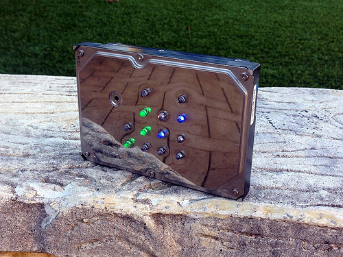
[Aaron] got creative for his clock enclosure, upcycling an old hard drive. All of the hard drive guts were removed and replaced with his own electronics. The front cover had 13 holes drilled out for the LED’s. There are six green LED’s to display the hour, and seven blue LED’s for the minute. The LED’s were wired up as common cathode. Since the hard drive cover is conductive, [Aaron] covered both sides of his circuit board with electrical tape and hot glue to prevent any short circuits. The end result is an elegant binary clock that any geek would be proud of.

The first Radar Arduino Shield

The First Arduino Radar Shield

The very first fully operational radar Arduino shield was recently demonstrated at Bay area Maker Faire. It was built by [Daniel] and [David], both undergrads at UC Davis.

Many have talked about doing this, some have even prototyped pieces of it, but these undergrad college students pulled it off. This is the result from Prof. ‘Leo’ Liu’s full-semester senior design course based on the MIT Coffee Can radar short course, which has been going on for 2 years now. Next year this course will have 30 students, showing the world the interest and market-for project based learning.

Check out the high res ranging demo, where a wider band chirp was used to amazing results. Video below.
Continue reading “The First Arduino Radar Shield”

Do You Have Any Idea How Fast Your Blender Was Going?

blenderSpeed 
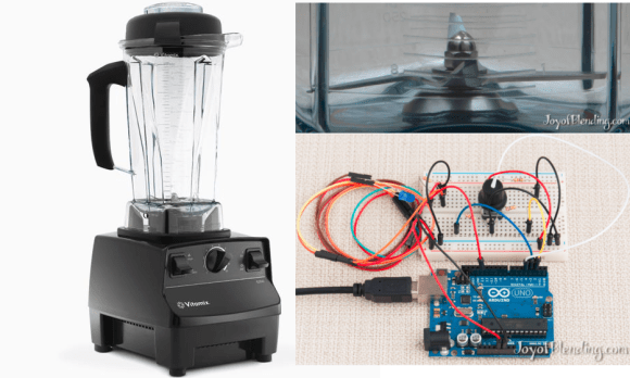
Some people really love their smoothies. We mean really, really, love smoothies and everything about making them, especially the blenders. [Adam] is a big fan of blenders, and wanted to verify that his Vitamix blenders ran as fast as the manufacturer claimed. So he built not one, but two speed measuring setups. Scientific blender measurement method requires one to cross check their results to be sure, right?

Measuring the speed of a blender is all about the RPM. Appropriately, [Adam’s] first measurement tool was an LED based stroboscope. Stroboscopes have been around for hundreds of years, and are a great way to measure how fast an object is rotating. Just adjust the speed of a flashing light until the rotating object appears frozen. The number of blinks per second is then equal to the Rotations Per Second (RPS) of the object being measured.Multiply by 60 seconds, and you’ve got RPM. [Adam] used an Arduino as the brains behind his stroboscope. He wired a dial up on his breadboard, and used it to adjust the flash rate of an LED. Since this was a quick hack, [Adam] skipped the display and just used the Arduino’s USB output to display speed measurements on his laptop.

There are possibilities for error with stroboscopes. [Adam] discovered that if the stroboscope was flashing at a multiple of the blade’s rotation speed, the blades would appear frozen, and he’d get an erroneous RPM value. Thankfully, [Adam’s] Vitamix had asymmetric blades, which made the test a bit easier. He calculated his blades to be spinning at 380 RPS, or 23,000 RPM. Not satisfied with his results, [Adam] brought out Audacity, and ran a spectral analysis of the blender in operation. He found a peak at 378Hz, which was pretty darn close to his previous measurement. Since the blender has a 4 inch blade this all works out to a blade tip speed right around the claimed value of 270 MPH. We’re glad [Adam] found an answer to his blender questions, but our personal favorite blender hack still has to be the V8 blender created by the Top Gear crew.   [via HackerNews]

640×480 VGA On An Arduino

There are dozens, if not hundreds of examples around the Intertubes of an Arduino generating a VGA video output. The Arduino isn’t the fastest chip by far, and so far, all of these VGA generation techniques have peaked out at lower resolutions if you want to control individual pixels.[PK] has an interesting technique to generate 640×480 VGA at 60 frames per second without overclocking. It’s hacky, it’s ugly, but surprisingly, it actually works.

The VGA standard of 640×480 @ 60 fps requires pixels to be clocked out at 25.175 MHz, and the ATMega chips found in Arduinos top out at 20 MHz. [PK] wanted to generate VGA signals without overclocking, He did this by doubling the clock frequency with digital logic. The ATMega generates a clock, an inverter delays that clock so it is 90 degrees out of phase, and the two clocks are XORed, doubling clock output of the micro. It produces a very ugly square wave at 32 MHz – an error of 27% compared to the VGA spec. Somehow it still works.

With a hilariously out of spec clock, the rest of the project was pulled together from [Nick Gammon]’s VGA library, a 16×16 font set, and a project from [lft]. Video below.

Continue reading “640×480 VGA On An Arduino”

Beating Simon

Virtually everyone has played Simon, that electronic memory game from the 70s, but who among us has actually beaten it? That was the goal of [Ben] and his 7-year-old daughter, and after a year of work, an Arduino, some servos, and a few Lego bricks, they’ve finally done it.

Instead of the large original Simon, [Ben] is using a key chain version of the game: much smaller, and much easier to build a device to sense the lights and push the buttons. The arms are made from Lego bricks, held up with rubber bands and actuated with two servos mounted on a cutting board.

To detect Simon’s lights, [Ben] connected four phototransistors to an Arduino. The Arduino records the pattern of lights on the Simon, and activates the Lego arms in response to that pattern. [Ben]’s version of Simon has only a maximum of 32 steps in the final sequence, but that still means each game takes 528 button presses – and a lot of annoying beeps – to complete.

Videos below.

Continue reading “Beating Simon”

Track Your Dog With This DIY GPS Harness

GPS-dog-harness

Have you ever wondered how far your dog actually runs when you take it to the park? You could be a standard consumer and purchase a GPS tracking collar for $100 or more, or you could follow [Becky Stern’s] lead and build your own simple but effective GPS tracking harness.

[Becky] used two FLORA modules for this project; The FLORA main board, and the FLORA GPS module. The FLORA main board is essentially a small, sewable Arduino board. The GPS module obviously provides the tracking capabilities, but also has built-in data logging functionality. This means that [Becky] didn’t need to add complexity with any special logging circuit. The GPS coordinates are logged in a raw format, but they can easily be pasted into Google Maps for viewing as demonstrated by [Becky] in the video after the break. The system uses the built-in LED on the FLORA main board to notify the user when the GPS has received a lock and that the program is running.

The whole system runs off of three AAA batteries which, according to [Becky], can provide several hours of tracking. She also installed a small coin cell battery for the GPS module. This provides reserve power for the GPS module so it can remember its previous location. This is not necessary, but it provides a benefit in that the GPS module can remember it’s most recent location and therefore discover its location much faster. Continue reading “Track Your Dog With This DIY GPS Harness”

A Tweeting Litter Box

SmartLitterBox

How can you not be interested in a project that uses load cells, Bluetooth, a Raspberry Pi, and Twitter. Even for those of our readers without a cat, [Scott’s] tweeting litter box is worth the read.

Each aspect of this project can be re-purposed for almost any application. The inexpensive load cells, which available from eBay and other retailers, is used to sense when a cat is inside the litter box. Typically sensors like the load cell (that contain a strain gauge) this use a Wheatstone bridge, which is very important for maximizing the sensitivity of resistive sensor. The output then goes to a HX711, which is an ADC specifically built for load cells. A simple alternative would be using an instrumentation amplifier and the built-in ADC of the Arduino. Now, the magic happens. The weight reading is transmitted via an HC-06 Bluetooth module to a Raspberry Pi. Using a simple Perl script, the excreted weight, duration, and the cat’s resulting body weight is then tweeted!

Very nice work! This is a well thought out project that we could see being expanded to recognize the difference between multiple cats (or any other animal that goes inside).