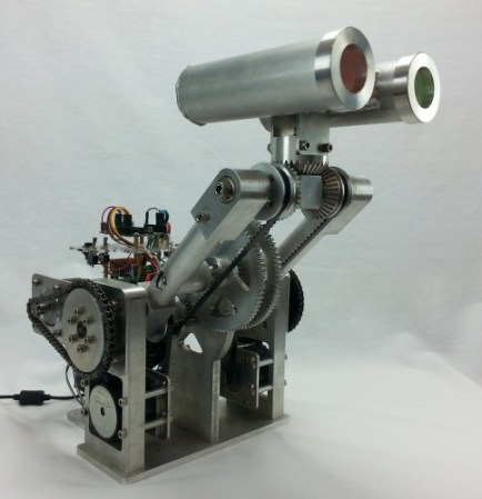
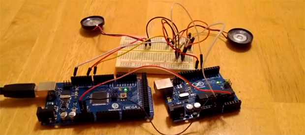
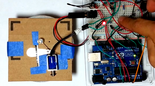
Modifying The HC-05 Bluetooth Module Defaults Using AT Commands

The HC-05, a Bluetooth to serial bridge, can be found for around $5 on the internet and therefore may be the cheapest way to add Bluetooth connectivity to your project.

However, its default settings may need to be changed depending on your application. [Hazim] explains a way to enter the HC-05 AT command mode to benefit from the rich set of features that the device can provide. The process is fairly simple as it only consists of maintaining the key pin of the HC-05 high while powering on. The device then boots in AT command mode with a default 38400bits/s speed and listens for all of the AT command set (PDF). As an example [Hazim] provides a sketch allowing you to write the AT commands directly in your favorite terminal.

With the basics out of your way you may want to further research the hardware, especially if you will be using modules from different sources. They don’t always come with the same firmware.

RGB Infinity Mirror

If you’ve been waiting for a more detailed guide before you set off to work on your own Infinity Mirror, [Ben]’s write-up is perhaps the most approachable one you will find. This build uses a set of four potentiometers to control an analog RGB LED strip (these lights are not individually addressable: but that makes coding simpler). [Ben] powers everything from a 12V 5A DC adapter, which is more than enough to run the 12V RGB strip along with the Arduino.

The mirror has two different ‘modes:’ individual channel color control and color-fade. In the first mode, three pots drive the RGB channels respectively. The color-fade mode has a mind of its own, sliding between all possible colors; you can spin the fourth potentiometer to control the speed of the transition.

The video below better illustrates the different modes. We definitely recommend [Ben’s] excellent guide as an ideal first project for anyone who has yet to take the plunge beyond simple microcontroller exercises. Check out Freeside Atlanta’s Infinity Mirror prototype for more inspiration.

Continue reading “RGB Infinity Mirror”

Another Arduino Clone Is The Last Thing The World Needs

duino

One might think the last thing the world needs is for The Great Old Ones to rise from their near-death sleep deep in the Pacific ocean, and begin again their reign over Earth.  Actually, the last thing the world needs is another Arduino clone. Here’s this one. Fittingly, it’s called the Ktuluino.

Actually, this isn’t yet another attempt to build an Arduino clone that adds nothing to existing designs; it’s just [Jeff]’s attempt at PCB design. He needed something to practice on, so why not something that ends in -uino?

The board is just about as simple as Arduinos come – an ATMega328P is the brains of the outfit and also the most expensive component, closely followed by either the power jack or the header pins. As an exercise in PCB design, we’ll give this a thumbs up, but this could also be used for an ‘introduction to soldering’ workshop at a hackerspace, or alternatively a coaster.

A Real Car Remote Controlled With An Arduino… What Could Go Wrong?

[Gilad] tipped us about his latest project, where he adds plenty of pneumatics and electronics into his wife’s car to remote control it.

The brake/throttle pedals are actuated by pistons controlled by electronic valves, and a standard DC motor is in charge of turning the wheel. The Arduino code tells us that the valves will be opened as long as the remote up/down channel is above/under given values. The frame is based on Festo aluminium profiles and we’re not sure where the mains used for the DC/DC converters is coming from.  As the valves use 24V and the motor 12V, standard N-Mosfets and power relays are used for voltage conversion. The remote controller [Gilard] used is actually 20 years old, so the output signal of the receiver isn’t actually really clean.

We do hope to never see this car on the road….

Obstacle Avoiding LEGO Rover Uses CDs For Wheels

lego-rover

This rover built by [Sath02] is a great example that you don’t have to be a mechanical engineering wizard to get into robotics. He used LEGO pieces to help ease the difficulty of getting a rover up and running.

In this case the use of LEGO is strictly structural. The electronics are not the NXT parts you would expect to see when working with these popular toy blocks. Instead he’s put the Arduino Palm Plus into service. It’s an Arduino board that has rows of holes at either end to make it LEGO compatible. It also carries an LM293D motor controller and [Sath02] added an XBee module for wireless control.

At the top of the assembly is an IR distance sensor which is used for obstacle avoidance. You may not be interested in building and exact replica, but the techniques he uses for attaching the distance sensor, CD wheels,  and fabricating the rest of the rover are good examples if you take on a LEGO build in the future.

Continue reading “Obstacle Avoiding LEGO Rover Uses CDs For Wheels”

Yet Another Self-Balancing Unicycle

No one has time to hone their balancing skills these days, and if building your own Segway doesn’t generate enough head-turning for you, then the self-balancing unicycle from the guys at [Scitech] should. Their build is chain-driven, using easy-to-find salvaged Razor scooter parts. Throw in a motor controller, 5DOF IMU and some batteries and it’s almost ready to burn up the sidewalks in hipster-tech style.

Some of the previous unicycle builds we’ve seen are a little on the bulky side, but the [Scitech] cycle aims for simplicity with its square tube steel framing and footrests. As always, unicycle builds like these take some effort on behalf of the rider: shifting your weight controls steering and throttle. The [Scitech] gang also discovered that it’s usually best when you don’t accidentally wire the motors up to the controller backwards. We recommend that you find a helmet and watch the video after the break.

Too-cool-for-unicycle hackers can build a dangerously fast e-skateboard instead.

Continue reading “Yet Another Self-Balancing Unicycle”

Learn JTAG By Writing A Bit-banging Programmer

j-tag-flow-chart

[Pesco] won one of Dangerous Prototypes’ PCB giveaways a few months ago. He opted for a CPLD breakout board. He just needed to put in a parts order and populate the components himself. But then what? He needed a JTAG programmer to work with the chip. Like any good autodidact he choose to make his own rather than buying one. He absorbed the JTAG specification and coded a bit banging programmer using an Arduino.

We’ve used JTAG many times to program ARM chips. But until now we never took the time to figure out how the specification works. If you’ve got an IEEE subscription you can download the whitepaper, but [Pesco] was also able to find one floating around on the interwebs. The flow chart on the left is the cheat sheet he put together based on his readings. From there he wrote the Arduino sketch which implements the programming standard, allowing him to interact with a chip through a minicom terminal window.

[via Dangerous Prototypes]