8-pin Micro Plays Pong On Your Widescreen

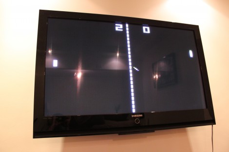
[Fernando] sent in a tangential project update that uses an ATtiny45 to play Pong on his television. Last time we looked in on his work he had just finished getting the eight-pin chip to display a big number on the TV via the VGA port. This expands on the idea while he continues to wait for parts.

Right now the chip plays against itself, but he’s got one input pin left and we’d love to see a button added for a simple one-player game. We’re thinking the paddle would always be moving in one direction or the other, with a click of the button to reverse that direction. The part that he’s waiting for is a Bluetooth module, which we’d love to see used for 2-player games via a pair of Wiimotes (we’re just wishing at this point and don’t know if that would even be possible). The end goal for the hardware is a Bluetooth connected scoreboard for Android devices.

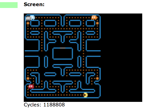
The code is written in Assembly, and we found it relatively easy to follow what [Fernando] is doing with the game logic. On the graphics side of things he gets away with a 120×96 resolution because Pong is supposed to look pixelated. We love the result, which you can see for yourself after the break.

Continue reading “8-pin Micro Plays Pong On Your Widescreen”

ATtiny Hacks: ATtiny10 Game – Doing More With Less

ATtiny Hacks Theme Banner

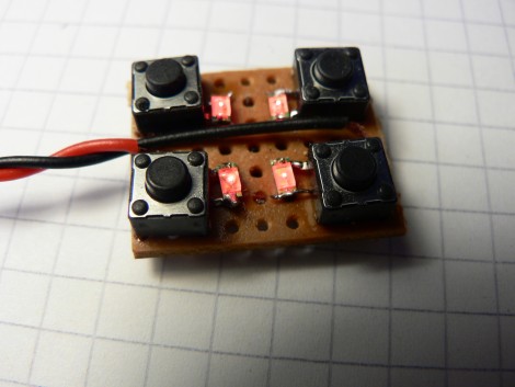
Okay, you’ve got a six-pin microcontroller with 1k of program memory, 32 bytes of SRAM, and it can’t be programmed using an In-System-Programmer. Do you think you can use it to develop a game? [Wrtlprnft] managed to build a Simon Says game based on the diminutive device that has four buttons and four LEDs. Judging from the video after the break, we’d say he nailed it!

There are so many design challenges here. First off, with only six pins total getting eight devices connected and working means doubling up on each I/O pin and using the reset pin as a doubled-up I/O. We’ve seen momentary push buttons on the same pins as LEDs before, so that’s not too hard to get working.

But if you’re using the reset pin how do you flash the thing? It doesn’t use the same ISP programming protocol that it’s bigger cousins do, so [Wrtlprnft] used an ATmega1284P to program it, hooking up to the three I/O pins and using a transistor to push 12V on the reset pin. But there’s still the matter of writing the code. It has half of the 32 registers you’d expect to find. He ended up ditching C and went straight to writing Assembly because of the diminished instruction set. It’s the first thing he’s written in Assembly, and a great way to learn the ropes.

It may not be as polished, but we do like it just as much as the Karate Chop Simon Says game which has a lot of other bells and whistles.

Continue reading “ATtiny Hacks: ATtiny10 Game – Doing More With Less”

Have You Got What It Takes To Code Android Apps Using Assembly?

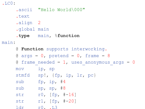
Do you have a rooted Android device and a computer running Linux? If so, you’re already on your way to coding for Android in Assembly. Android devices use ARM processors, and [Vikram] makes the argument that ARM provides the least-complicated Assembly platform, making it a great choice for those new to Assembly programming. We think his eight-part tutorial does a great job of introducing the language and explaining how to get the development tools up and running. You’ll need to know some basic programming concepts, but from what we saw you don’t need any prior experience with ARM or Android.

So why learn Assembly at all? We took a stab at Assembly for AVR a few months ago and really learned a lot about the hardware that we just never needed to know writing in C. It’s a great way to optimise functions that waste too much time because of quirks with higher-level language compilers. That means you don’t need to write your entire application in Assembly. You can simply use it to streamline hairy parts of your code, then include those Assembly files at compile time.

A Study In AVR Power Saving Techniques

amtel_avr

[Scott] found the iCufflinks from Adafruit Industries pretty interesting, but he thought that the stated run time of 24 hours was a bit short. He figured he could improve the product’s power consumption at least a little bit, to improve the overall battery life.

From their schematics, he placed an order for parts and built two identical iCufflink mock-ups side by side – one running their code and one running his. He took baseline current draw measurements, then got busy slimming down the cufflinks’ software. It had been 20 years since he touched assembly, and he has never written it for an AVR, but judging by his work he’s not rusty in the least.

He slowed the ATtiny’s clock down and tweaked a few other settings for a savings of 53μA, but the real improvements came via a fairly simple fix. The original code called for the processor to institute a counting loop to sleep, which he found to be very wasteful. Instead, he chose to put the processor in an idle state, using the chip’s watchdog timer to wake it when it was time to pulse the LED. The power savings from this change alone was a whopping 261μA!

When he was said and done, the changes save about 315μA of current draw, and should allow the cufflinks to run for up to 38 hours without swapping batteries. In [Scott’s] opinion, a nearly 60% improvement in battery life is pretty good for a day’s work, and we’re inclined to agree.

EvalBot: Arrival And Assembly

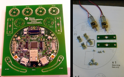
[Chris Muncy] just received his EvalBot from TI and took some pictures of the assembly process. He was one of the lucky folks that picked up the kit for just $25 using a short-lived coupon code. Seeing the kit makes us wish we had ordered one. There is some assembly required but as you can see, it’s pretty much just mechanical assembly of the wheels and the front bumper arms.

We think the wheel design is quite good. It consists of two small gearhead motors mounted on the rectangular PCB parts that you can see on the right portion of the image above. Those mount to the circular mainboard using metal L brackets. The wheels themselves are three circular pieces of PCB, one with a smaller diameter sandwiched in between its two larger cousins. This creates a channel that is perfect for a neoprene O-ring to give the wheel traction. The main board uses an optical sensors and a hole through all three parts to function as a rotation counter.

It’s a fancy piece of hardware and we can’t wait to see what you can do with it! If you’ve got one, we want to hear about your adventures.

Open Call: Send Us Your Debounce Code

If you’ve ever designed an embedded system with at least one button you’ve had to deal with button debouncing. This is also know as contact bounce, a phenomenon where a button press can be registered as multiple button presses if not handled correctly. One way to take care of this is with a hardware filter built from a resistor-capacitor setup, or by using a couple of NAND gates. We find that [Jack Ganssle] put together the most comprehensive and approachable look at contact bounce which you should read through if you want to learn more.

We’re interested in software solutions for debouncing buttons. This seems to be one of the most common forum questions but it can be hard to find answers in the form of reliable code examples. Do you have debounce code that you depend on in every application? Are you willing to share it with the world? We’d like to gather as many examples as possible and publish them in one-post-to-rule-them-all.

Send your debounce code to: debounce@hackaday.com

Here’s some guidelines to follow:

  • Please only include debounce code. Get rid of other unrelated functions/etc.
  • You should send C code. If you want to also send an assembly code version that’s fine, but it must be supplementary to the C code.
  • Please comment your code. This will help others understand and use it. You may be tempted to explain the code in your email but this info is best placed in the code comments
  • Cite your sources. If you adapted this code from someone else’s please include a note about that in the code comments.

As an example we’ve included one of our favorite sets of debounce code after the break. Please note how it follows the guidelines listed above.

Continue reading “Open Call: Send Us Your Debounce Code”

2-bit Paper Processor Teaches How They Work

Take a few minutes out of your day, grab your scissors, and learn how a simple processor works. [Saito Yutaka] put together an exercise to teach processor operations with paper. After downloading the PDF you can cut out the Address and Data pointer as well as two-bit data tokens for each. The processor has three instruction sets; Increment register by one, Jump if not over flow, and Halt wait for reset.

Once you’ve got your cutouts you can follow along as the program is executed. The INC operation is run, with the JNO used to loop the program. Once the register has reached an overflow the overflow counter halts the program.

One word of warning, we think there’s a typo in one of the captions.  Once the program starts running and gets to address 01(2) the caption still reads 00(2) for both address and data. As long as you compare the values in the picture along the way you should have no problem getting through execution. which has now been fixed.