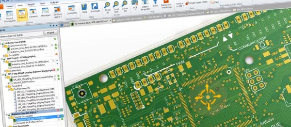
Mihir Shah has designed many a PCB in his time. However, when working through the development process, he grew tired of the messy, antiquated methods of communicating design data with his team. Annotating photos is slow and cumbersome, while sending board design files requires everyone to use the same software and be up to speed. Mihir thinks he has a much better solution by the name of InspectAR, it’s an augmented reality platform that lets you see inside the circuit board and beyond which he demoed during the 2019 Hackaday Superconference.
The idea of InspectAR is to use augmented reality to help work with and debug electronics. It’s a powerful suite of tools that enable the live overlay of graphics on a video feed of a circuit board, enabling the user to quickly and effectively trace signals, identify components, and get an idea of what’s what. Usable with a smartphone or a webcam, the aim is to improve collaboration and communication between engineers by giving everyone a tool that can easily show them what’s going on, without requiring everyone involved to run a fully-fledged and expensive electronics design package.
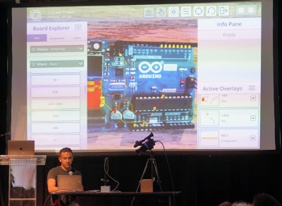
The Supercon talk served to demonstrate some of the capabilities of InspectAR with an Arduino Uno. With a few clicks, different pins and signals can be highlighted on the board as Mihir twirls it between his fingers. Using ground as an example, Mihir first highlights the entire signal. This looks a little messy, with the large ground plane making it difficult to see exactly what’s going on. Using an example of needing a point to attach to for an oscilloscope probe, [Mihir] instead switches to pad-only mode, clearly revealing places where the user can find the signal on bare pads on the PCB. This kind of attention to detail shows the strong usability ethos behind the development of InspectAR, and we can already imagine finding it invaluable when working with unfamiliar boards. There’s also the possibility to highlight different components and display metadata — which should make finding assembly errors a cinch. It could also be useful for quickly bringing up datasheets on relevant chips where necessary.
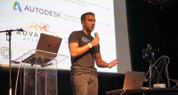
Obviously, the electronic design space is a fragmented one, with plenty of competing software in the market. Whether you’re an Eagle diehard, Altium fanatic, or a KiCad fan, it’s possible to get things working with InspectAR. Mihir and the team are currently operating out of office space courtesy of Autodesk, who saw the value in the project and have supported its early steps. The software is available free for users to try, with several popular boards available to test. As a party piece for Supercon, our very own Hackaday badge is available if you’d like to give it a spin, along with several Arduino boards, too. We can’t wait to see what comes next, and fully expect to end up using InspectAR ourselves when hacking away at a fresh run of boards!


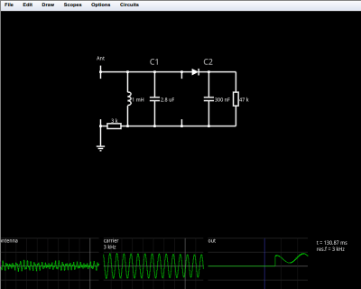 Like the original simulator, this one is great to show a classroom circuits and encourage building or studying circuits in the browser. There’s no extra software to install, which is handy for an impromptu demo. Another cool feature is the visualization of current flow as animated dots. The dots move in the direction of the current flow and the speed of motion is proportional to the amount of current. Watching a capacitor charge with the moving dots is very illustrative. You can also view data in a scope format or hover the mouse over things to read their values.