Homebrew Relay Computer Features Motorized Clock

Before today, we probably would have said that scratch-built relay computers were the sole domain of only the most wizardly of graybeards. But this impressive build sent in by [Will Dana] shows that not only are there young hardware hackers out there that are still bold enough to leave the transistor behind, but that they can help communicate how core computing concepts can be implemented with a bundle of wires and switches.

Created for his YouTube channel WillsBuilds, every component of this computer was built by [Will] himself. Each of the nine relay-packed protoboards inside the machine took hours to solder, and when that was done, he went out to the garage to start cutting the wood that would become the cabinet they all get mounted in.

Continue reading “Homebrew Relay Computer Features Motorized Clock”

Saturday clock - 1 CPU clock cycle per day

Saturday Clock: An 0.000011574Hz ATtiny85 Clock

In these times when we try to squeeze out extra clock cycles by adding more cores to our CPUs and by enlisting the aid of GPUs, [Ido Gendel] thought it would be fun to go in the exact opposite direction, supply a clock to the ATtiny85 that cycles only once per day, or at 0.000011574Hz. What application could this have? Well, if he could do it in seven instructions or less, how about turning on an LED at sunset Friday evening, to indicate the start of the Jewish Shabbat (Saturday), and turn it off again at sunset Saturday evening.

Notice the subtlety. A clock that cycles once per day means you can execute at most one instruction per day. Luckily on AVR microcontrollers, the instructions he needed can execute in just one cycle. That of course meant diving down into assembly code. [Ido] wasn’t an assembly wizard, so to find the instructions, he compiled C code and examined the resulting assembly until he found what he needed. One instruction turns on the LED and the instruction immediately following turns it off again, which normally would make it happen too fast for the human eye to register. But the instruction to turn it on runs on Friday evening and the very next instruction, the one that turns it off, doesn’t run until Saturday evening. Do you feel like you’re in a science fiction story watching time slowed down? Freaky. A few NOPs and the jump for the loop take up the remaining five cycles for the week.

For the source of the clock he chose to use an LDR to detect when the light level dropped at the end of the day. The problem he immediately ran into was that clouds, bird shadows, and so on, also cause drops in the light level. The solution he found was to widen the light and dark range by adding a TLV3702 push-pull output comparator and some resistors. [Ido] gives a detailed explanation of the circuit in the video after the break.

Continue reading “Saturday Clock: An 0.000011574Hz ATtiny85 Clock”

Down The Rabbit Hole Of STM32 Clock Options

Once you venture beyond the tame, comfortable walls of the 8-bit microcontroller world it can feel like you’re stuck in the jungle with a lot of unknown and oft scary hazards jut waiting to pounce. But the truth is that your horizons have expanded exponentially with the acceptable trade-off of increased complexity. That’s a pretty nice problem to have; the limitation becomes how much can you learn.

Here’s a great chance to expand your knowledge of the STM32 by learning more about the system clock options available. We’ve been working with STM32 chips for a few years now and still managed to find some interesting tidbits — like the fact that the High Speed External clock source accepts not just square waves but sine and triangle waves as well, and an interesting ‘gotcha’ about avoiding accidental overclocking. [Shawon M. Shahryiar] even covers one of our favorite subjects: watchdog timers (of which there are two different varieties on this chip). Even if this is not your go-to 32-bit chip family, most chips have similar clock source features so this reading will help give you a foothold when reading other datasheets.

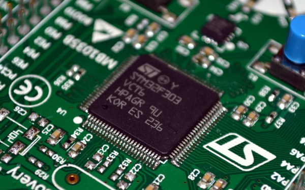
There is a clock diagram at the top of that post which is small enough to be unreadable. You can get a better look at the diagram on page 12 of this datasheet. Oh, and just to save you the hassle of commenting on it, the chip shown above is not an f103… but it just happened to be sitting on our desk when we started writing.

20 Pounds And A Gut Feeling Yields A Configurable Rubidium Atomic Clock Source

rubidium-source-for-twenty-pounds

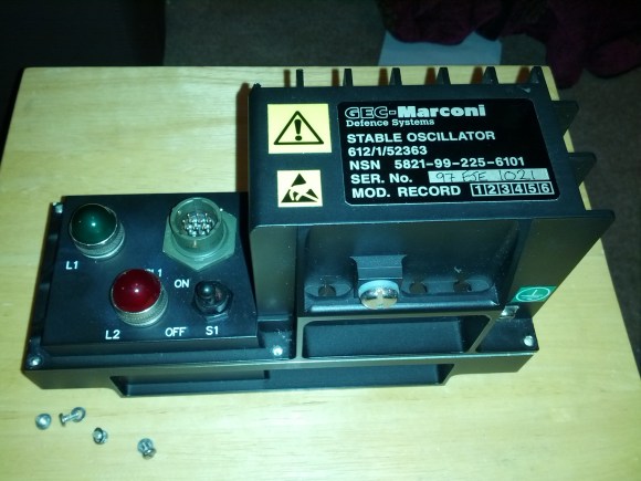
So you see an image like this and the description “Aircraft stable oscillator” on an eBay listing for twenty pounds (about thirty bucks), what do you do? If you’re [Alecjw] you buy the thing and crack it open to find an atomic clock source inside. But he really went the distance with this one and figured out how to reconfigure the source from the way it was set up in the factory.

First off, the fact that it’s made for the aerospace industry means that the craftsmanship on it is simply fantastic. The enclosure is machined aluminum and all of the components are glued or otherwise attached to the boards to help them stand up to the high-vibrations often experienced on a plane. After quite a bit of disassembly [Alec] gets down to a black box which is labeled “Rubidium Frequency Standard”… jackpot! He had been hoping for a 10 MHz signal to use with his test equipment but when he hooked it up the source was putting out 800 kHz. With a bit more investigation he figured out how to reconfigure the support electronics to get that 10 Mhz source. We think you’re going to love reading about how he used a test crystal during the reconfiguration step.

Once he knew what he had he returned to the eBay seller and cleared out the rest of his stock.

[Thanks DIY DSP]