Introducing The FleaFPGA Experimenter’s Board

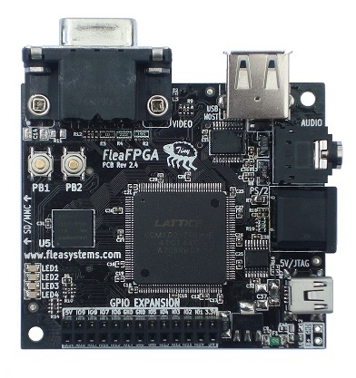
[Valentin] recently tipped us about an FPGA development board he just finished. It is called the FleaFPGA and is aimed to get people interested in the world of Field Programmable Gate Arrays. One of the other reasons that also got [Valentin] to design his own board was that he was frustrated with the existing solutions, them being either too pricey or fairly spare in terms of connectivity.

The main components that you can see in the platform shown above are: a lattice MachX02-7000HE FPGA (6864LUTs), 256Mbits of SDRAM, a USB2.0 host port, a 4096-color VGA connector, a 3.5mm stereo connector, an SD/MMC card slot, a PS/2 keyboard/mouse combo port, a few push buttons and LEDs. An expansion header is also present in order to connect the FleaFPGA to future shields that will be developed. Unfortunately only the board schematics have been released and [Valentin] is currently aiming for a price of $60 per board for <100 quantities. You’ll be able to see a video of the board in action after the break, in which the FPGA has been loaded with a 68000 software core running a variation of the Amiga Juggler Demo.

Continue reading “Introducing The FleaFPGA Experimenter’s Board”

Sega Master System On A STM32 Development Board

Sega on STM32

Some hackers have managed to convert an STM32 development into a Sega Master System emulator. This means Sonic the Hedgehog running on an ARM Cortex-M4.

This hack has a number of parts. First, [Alessandro Rocchegiani] showed off a video of his Sega Master System emulator running on the STM32F429 Discovery development board. This first version used the on board 2.4″ TFT LCD screen.

[Fabrice] was working with this STM32 Discovery board already. He had developed an expansion board that added a number of features to the development kit, including an R-2R DAC for video output. When [Fabrice] found out about the Sega Master System emulator, he worked with [Alessandro] and his son [Fabrizio] to get VGA output working. They also added support for the Wii controller using [Fabrice]’s Wii library. The result is a Sega Master System emulator with VGA output at 640 x 480, with 16 bit color and Wii controller support.

You can watch a video of both the LCD and VGA versions of the hack after the break.

Continue reading “Sega Master System On A STM32 Development Board”

A $5 ARM Development Board

Most of you know that there are plenty of ARM powered development boards out there, so you may not be really sure what a new one can still bring to the table.

With a $5 price tag, the open hardware McHck (pronounced McHack) is meant for quickly building projects on a small budget. The board created by [Simon] is based on a Freescale Cortex M4 microcontroller, and can be plugged directly into one’s computer. As a Direct Firmware Update (DFU) bootloader is present on the microcontroller, there is no need for external programming equipment.

The board has unpopulated footprints that allow users to add other functionalities that may be required for their future projects: a Real Time Clock (RTC), a Boost regulator for single cell battery operation, Buck and linear regulators, a Lithium Polymer (LiPo) battery charger and even an External Flash storage.

The Bill of Materials can be found on the project wiki and the McHck community will soon launch a crowdfunding campaign to send the 5th version of the board to all the hobbyists that may be interested.

And if you’re curious, you can also have a look at all the other boards that Hackaday featured these last months: the browser based IDE arm boardquad-core ARM dev board and the Matchbox ARM.

Etch Your Own CPLD Development Board

etch-your-own-cpld-breakout

Ever wanted to make the jump from microcontrollers to logic chips? Although not technically the same thing we consider FPGA and CPLD devices to be in similar categories. Like FPGAs, Complex Programmable Logic Devices let you build hardware inside of a chip. And if you’ve got the knack for etching circuit boards you can now build your own CPLD development module. Long-time Hackaday readers will remember our own offering in this area.

Our years of microcontroller experience have taught us a mantra: if it doesn’t work it’s a hardware problem. We have a knack for wasting hours trying to figure out why our code doesn’t work. The majority of the time it’s a hardware issue. And this is why you might not want to design your own dev tools when just starting out. But one thing this guide has going for it is incremental testing. After etching and inspecting the board, it is populated in stages. There is test code available for each stage that will help verify that the hardware is working as expected.

The CPLD is programmed using that 10-pin header. If you don’t have a programmer you can build your own that uses a parallel port. Included on the board is an ATtiny2313 which is a nice touch as it can simulate all kinds of different hardware to test with your VHDL code. There is also a row of LEDs, a set of DIP switches, and a few breakout headers to boot.

DIY ARM Prototyping Board

We’re impressed by the ARM prototyping board which [Danjovic] is showing off. He proves that in this day of ever shrinking packages it’s still possible to make your own development tools with protoboard and a soldering iron.

To tell you the truth, if he had designed and etched his own board we probably wouldn’t have featured it. But he didn’t need to spend time on the layout, etching, and reflow. Instead it’s just some enamel wire and a lot of patience. The patience is because the NXP ARM Cortex-M0 chip comes in a HVQFN package. We’re not entirely sure about the HV part (the package alphabet was not entirely clear on this) but QFN means Quad Flat No-Lead. That means no legs on the chip. So [Danjovic] glued it upside down and soldered point-to-point to break out all of the pins.

The top side of the board has a bootloader button, reset button, power regulation, and a crystal oscillator. He doesn’t mention what bootloader he’s using, but a Nokia USB cable gives him the connectivity to push his programs onto the chip.

Making The Most Of Your Diy Development Boards

[Rajendra] built a rather impressive development board based around a PIC microcontroller. At its center, he’s got a PIC 16F1827 chip, but we think the design is easily adapted to your microcontroller of choice.

The I/O pins on the microcontroller aren’t actually connected to any of the components on the board. Instead, female pin headers neatly organize the pins grouped by their register. Jumper wires make for quick connections to all of the available peripheral devices. There’s an additional header for connecting the PICKit programmer, and the small blue breadboard lets you add your own components to the mix, or lets you utilize the board with a different microcontroller.

[Rajendra] took the time to carefully label all of the connectors, removing the guesswork (or pin counting) from the setup process. Many of the peripherals are i2c devices, and there’s a pin header to connect more, or to sniff the data using a Bus Pirate or other tool.

Quick And Easy DIY PIC Development Board

diy_pic_dev_board

A few months back, [Phil] was looking to get into PIC development, but he couldn’t seem to find a simple development board for the PIC16F883 microcontroller he wanted to use. Since no retail offering had exactly what he was looking for, he decided to put together a dev board of his own.

He spent a couple hours in Eagle, putting together a simple board layout. [Phil] then busted out the iron and copper clad, making his dev board a reality using the tried and true toner transfer method.

He says that the board itself is quite simple, consisting of little more than the PIC, an LM1117 linear voltage regulator, and all the pin headers you could possibly need. While very basic and not necessarily a hack, we do like seeing people make their own tools when the market doesn’t provide what they want.

If you have been looking around for a simple PIC development solution, be sure to swing by [Phil’s] site – all of the schematics and layout files are free for the taking.