30-Year-Old Macintosh SE/30 Gets A Brand New Logic Board

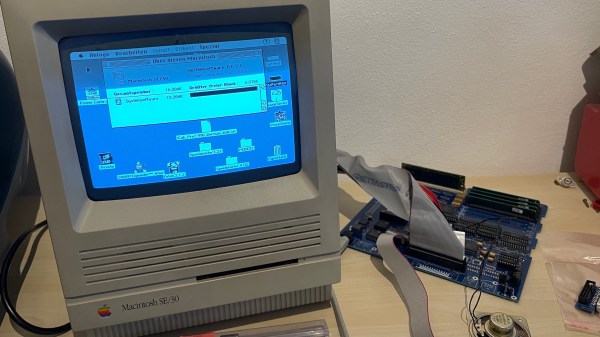
Some time ago, [Bolle] got the idea to redraw the Macintosh SE/30 schematics in Eagle. Progress was initially slow, but over the past month (and with some prodding and assistance from fellow forum frequenter [GeekDot]), he’s taken things a step further by creating a fully functional replacement Macintosh SE/30 logic board PCB.

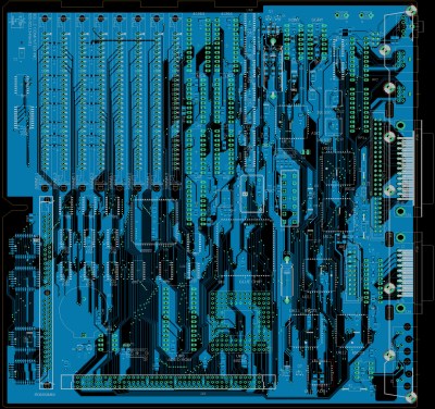
By using the available schematics, the project didn’t even require much reverse engineering. Though he plans for more modernization in later iterations, this design is largely faithful to the original components and layout, ensuring that it is at least basically functional. He did update the real time clock battery to a CR2032 and, as a benefit of redrawing all the traces, he was able to use a 4-layer PCB in place of the costly 6-layer from Apple’s design.

The board came back from fabrication looking beautiful in blue; and, once he had it soldered up and plugged in, the old Mac booted on the very first try! A copy-paste mistake with the SCSI footprints led to some jumper wire bodging in order to get the hard drive working, but that problem has already been fixed in the next revision. And, otherwise, he’s seen no differences from the original after a few hours of runtime.

Recreating old Macintosh logic boards almost seems like its own hobby these days. With the design and fabrication capabilities now accessible to hobbyists, even projects that were once considered professional work are in reach. If you’re interested in making your own PCB designs, there are many resources available to help you get started. Alternatively, we have seen other ways to modernize your classic Macs.

[Thanks to techknight for the tip!]

Friday Hack Chat: Eagle PCB Design With Matt Berggren

Eagle is a household name for all Hackaday regulars. Here’s your chance to learn about upcoming features, get your ‘how do I do this in Eagle?’ questions answered, and get your wishlist items heard. Join us on Friday at 12:00 PST for a live Hack Chat about the Eagle PCB Design software.

Hosting this week’s discussion is [Matt Berggren], also known on Hackaday.io as technolomaniac. Matt is the Director of Autodesk Circuits and with Autodesk’s acquisition of Eagle last summer, the popular schematic design and PCB layout software falls under his purview. He has an extensive background in designing printed circuit boards — if you can do it in EDA software he knows how — this is an excellent opportunity to get answered the questions that have been stumping you.

Don’t miss this Hack Chat! Here’s a handy web tool to help convert 1/13/17 at 12:00 PST to your local time.

Here’s How to Take Part:

join-project-team-message-buttons
Buttons to join the Hacker Channel and enter Hack Chat

Hack Chat are live community events that take place in the Hackaday.io Hacker Channel. Visit that page (make sure you are logged in) and look for the “Join this Project Button” in the upper right. Once you are part of the Hacker Channel, that button will change to “Team Messaging” which takes you to the Hack Chat.

You don’t have to wait for Friday, join Hack Chat whenever you like and see what the community is currently talking about.

Join Us Next Week Too for KiCad!

Are you more of a KiCad person than an Eagle person? You should still drop by this week to see if Matt changes your mind. But block out your calendar next week when [Wayne Stambaugh], one of the lead developers of KiCad will join us for a Hack Chat on Friday, 1/20/17.

Creating A PCB In Everything: Eagle DRC And Gerber Files

For the next post in the Creating A PCB series, we’re going to continue our explorations of Eagle. In Part 1,  I went over how to create a part from scratch in Eagle. In Part 2, we used this part to create the small example board from the Introduction.

This time around I’ll be going over Design Rule Check (DRC) — or making sure your board house can actually fabricate what you’ve designed. I’ll also be covering the creation of Gerber files (so you can get the PCB fabbed anywhere you want), and putting real art into the silkscreen and soldermask layers of your boards.

The idea behind this series is to explore different EDA suites and PCB design tools by designing the same circuit in each. You can check out the rest of the posts in this series right here.

Continue reading “Creating A PCB In Everything: Eagle DRC And Gerber Files”

Creating A PCB In Everything: Eagle, Part 2

In the last (and first) post in this series, we took a look at Eagle. Specifically, we learned how to create a custom part in Eagle. Our goal isn’t just to make our own parts in Eagle, we want to make schematics, boards, and eventually solder a few PCBs.

The board we’ll be making, like all of the boards made in this Creating A PCB In Everything series, is the Nanite Wesley, a small USB development platform based on the ATtiny85. This board has less than a dozen parts, most of which are through-hole. This is the simplest PCB I can imagine that has sufficient complexity to demonstrate how to make a board.

With that said, let’s get onto the second part of our Eagle tutorial and lay out our circuit board.

Continue reading “Creating A PCB In Everything: Eagle, Part 2”

Creating A PCB In Everything: Eagle, Part 1

For the first in a series of posts describing how to make a PCB, we’re going with Eagle. Eagle CAD has been around since the days of DOS, and has received numerous updates over the years. Until KiCad started getting good a few years ago, Eagle CAD was the de facto standard PCB design software for hobbyist projects. Sparkfun uses it, Adafruit uses it, and Dangerous Prototypes uses it. The reason for Eagle’s dominance in a market where people don’t want to pay for software is the free, non-commercial and educational licenses. These free licenses give you the ability to build a board big enough and complex enough for 90% of hobbyist projects.

Of course, it should be mentioned that Eagle was recently acquired by Autodesk. The free licenses will remain, and right now, it seems obvious Eagle will become Autodesk’s pro-level circuit and board design software.

Personally, I learned PCB design on Eagle. After a few years, I quickly learned how limited even the professional version of Eagle was. At that point, the only option was to learn KiCad. Now that Eagle is in the hands of Autodesk, and I am very confident Eagle is about to get really, really good, I no longer have the desire to learn KiCad.

With the introduction out of the way, let’s get down to making a PCB in Eagle.

Continue reading “Creating A PCB In Everything: Eagle, Part 1”

The Future Of Eagle CAD

Last week, Autodesk announced their purchase of CadSoft Eagle, one of the most popular software packages for electronic design automation and PCB layout.

Eagle has been around for nearly thirty years, and has evolved to become the standard PCB design package for electronic hobbyists, students, and engineering firms lead by someone who learned PCB design with Eagle. The reason for this is simple: it’s good enough for most simple designs, and there is a free version of Eagle. The only comparable Open Source alternative is KiCad, which doesn’t have nearly as many dedicated followers as Eagle.  Eagle, for better or worse, is a standard, and Open Source companies from  Sparkfun to Adafruit use it religiously and have created high-quality libraries of parts and multiple tutorials

I had the chance to talk with [Matt Berggren], former Hackaday overlord who is currently serving as the Director of Autodesk Circuits. He is the person ultimately responsible for all of Autodesk’s electronic design products, from Tinkercad, 123D, Ecad.io, and project Wire, the engine behind Voxel8, Autodesk’s 3D printer that also prints electronics. [Matt] is now the master of Eagle, and ultimately will decide what will change, what stays the same, and the development path for Eagle.

Continue reading “The Future Of Eagle CAD”

Escape Cable Hell With An Audio I/O Multiplexer

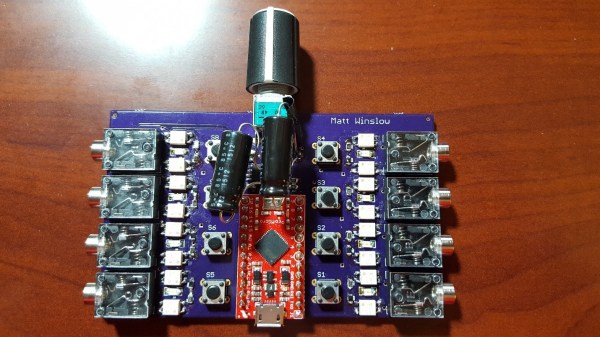
If you ever find yourself swapping between a mix of audio inputs and outputs and get tired of plugging cables all the time, check out [winslomb]’s audio multiplexer with integrated amplifier. The device can take any one of four audio inputs, pass the signal through an amplifier, and send it to any one of four outputs.

The audio amplifier has a volume control, and the inputs and outputs can be selected via button presses. An Arduino Pro Mini takes care of switching the relays based on the button presses. On the input side, you can plug in devices like a phone, TV, digital audio player or a computer. The output can be fed to speakers, headsets or earphones.

At the center of the build lies a TI TPA152 75-mW stereo audio power amplifier. This audio op-amp is designed to drive 32 ohm loads, so performance might suffer when connecting it to lower impedance devices, but it seems to work fine for headphones and small computer speakers. The dual-gang potentiometer controls the volume, and the chip has a useful de-pop feature. The circuit is pretty much a copy of the reference shown in the data sheet. Switching between inputs or outputs is handled by a bank of TLP172A solid state relays with MOSFET outputs, and it’s all tied together with a micro-controller, allowing for WiFi or BLE functionality to be added on later.

[winslomb] laid out the design using Eagle and he made a couple of footprint mistakes for the large capacitors and the opto-relays. (As he says, always double-check part footprints!) In the end, he solder-bridged them on to the board, but they should probably be fixed for the next revision.

[winslomb] built the switch as his capstone project while on his way to getting a Masters in EE, and although the device did function as required, there is still room for improvement. The GitHub repository contains all the hardware and software sources. Check out the video below where he walks through a demo of the device in action. If you are looking for something simpler, here is a two input – one output audio switcher with USB control and on the other end of the spectrum, here’s an audio switch that connects to the Internet.

Continue reading “Escape Cable Hell With An Audio I/O Multiplexer”