Altium Gives Away The Farm With New Circuit Maker Software

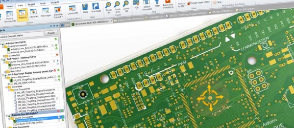
Things are about to get interesting in the world of PCB design software for the open source hardware community. This week, Altium launched the open public beta for its new Circuit Maker software, and it’s a major change from what we looked at previously. Everything is free.

You heard that right, free. Unlimited board size, and unlimited layers – all free. And this isn’t some stripped-down, bare-bones software here. They’ve thrown in almost everything under the sun; a 3D viewer, team project collaboration, EagleCAD and DFX import, integrated Octopart supplier and pricing information, no commercial usage limits, and project sharing. And if that isn’t enough, the “engine” seems to be the exact same back-end that is used in the full $10,000 Altium Designer as well(with a bit easier to use user interface on top). This is a major departure from the pre-beta we covered back in September. Altium was going have board size and layer limits, with the ability to “upgrade” at a cost. So by now you’re thinking to yourself “OK, what’s the catch?” Well there are a few gotchas – but only a few.

The software uses cloud based storage for your project files, and is community based. It won’t work without an Internet connection, there is no local storage, and it forces you to share your projects with the world. You do get two “Sandbox” designs that you can hide from the world before you generate your gerber files, but after that, your project is online for the whole world to see. Will that be a deal killer for the OSHW community? We’ll find out soon enough.

One thing is for sure, anyone with a doggy Internet connection is not going to enjoy using Circuit Maker (we’re hoping they remove that limitation in the final product). And as with any cloud based service, we wonder how many people will be willing to trust their designs to a free service that could be turned off on a whim? Or will the unlimited board size and layers, combined with Altium’s name and robust software win people over in the end?

If you want to see in-depth review of Circuit Maker, we highly recommend you watch the video after the break.  [Dave Jones] of the eevblog, gives you a full rundown on the beta version. Dave’s in a unique place to review this software, not only has he been using Altium since the mid-80’s as a professional engineer, he’s also a former Altium employee.

Continue reading “Altium Gives Away The Farm With New Circuit Maker Software”

EagleUp Pulls Your PCBs Into SketchUp

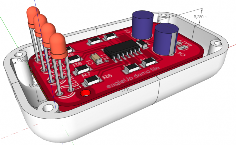
[Karl] wrote in to tell us about a software package called EagleUp that will import your Eagle CAD PCB designs into Google SketchUp. It bridges the gap between the two using the open source image processing software ImageMagick.

As you can see above, you’ll end up with a beautifully rendered 3D model of your hardware. This is a wonderful way to make sure that your enclosure designs are going to work without needing to wait for the PCBs to arrive from the fab house. It is available for Windows, OSX and Linux (although the last time we tried to run Sketchup under Wine nothing good came of it — perhaps it’s time to try again).

In [Karl’s] case, he’s working on an Arduino compatible board based around the Xmega. He mentions that EagleUp is a great way to get an idea of how component placement will end up, and to see if the silk screen layer is going to turn out well or not. Here’s a link to one of his test designs.

Video: Eagle CAD Layout

This week’s video is the last in a series of videos where we show how to use Eagle CAD. Today we will look a the Layout portion of the program and will create a circuit board from the schematic that we created previously. We start by creating a layout file and then moving all of the parts to appropriate places on the circuit board. After that, [Jack] shows how to route the traces. Along the way, he talks about the tools that he is using and various ways to use them. The end result is a prototyping board for the PIC18F44J11.

Like the others, this video is fairly long at 29 minutes, so make sure to have some time dedicated towards watching it if you do.

In next week’s video, we will be showing this board as it arrived to us from a manufacturer and will do a tutorial on how to solder.

If you have missed our previous videos, you can find them here:

Schematic part I
Schematic and Custom part creation
CAM Processor

We have also created many supplemental videos explaining how to use many of the tools in the tool palettes. You can find them on our Youtube channel:

Check out the video after the break!
Continue reading “Video: Eagle CAD Layout”

Video – Eagle CAD’s CAM Processor

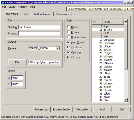
Here is the next installment in our series of Eagle CAD videos. In this video we skip ahead a bit and show off the CAM processor that you use to create the files necessary to have your circuit boards be manufactured. After watching this video, you will know how create a new CAM program, load a circuit board into the CAM processor, tell it where to save your files, and actually use it to create the files.

We’re skipping ahead today because of a screw up on our part. We meant to show the layout portion of the program today but edited the wrong video… We’ll show layout next week. After that, we will show the completed circuit board and solder the parts onto it.

If you are itching for some Eagle CAD layout info, you may be interested in some supplementary videos that we have uploaded to our Youtube channel. In those videos, we show how to use the most important features in the layout portion of the Eagle CAD.

Have you missed the previous videos? Here are some links to them:

Schematic and the beginning of a custom part: [click here]
More custom part stuff: [click here]

Video is after the break:
Continue reading “Video – Eagle CAD’s CAM Processor”

Arduino Shield Scaffold

arduinoshield

[Garrett] from macetech has been prototyping shields for the Arduino development platform. Arduino’s have an inexplicable nonstandard spacing between two of the banks of output pins. This means that you can’t use regular perfboard with them. To make the design process quicker, [Garrett] has put together an Eagle file that just includes the male header pins. The file also has a line indicating the tall lower board components so you can avoid creating shorts.

Hackaday Design Challenge – Yes, A Contest!


So, you guys want to show off your skills? We’re giving you the chance. [If you don’t like it, blame Limor – she came up with the original idea]

The Challenge:
Design our next give-away: a business card sized PC Board. We’re not telling you what to make the circuit do, just make it something handy for hacking. Me, I think a PIC programmer/proto board would be handy.

The board must have:

  • The Hackaday logo
  • business card dimensions (90mm x 55mm)
  • reasonably easy to construct
  • A useful circuit (programmer, interface, whatever.)
  • Assembly instructions
  • Parts list

Through hole components are a good idea (Of course, if you can do it with SMD cheaper, and keep it easy to build… Surprise us) Maybe we could surface mount the CPU before we give them away, or we might put together parts kits, but it depends on the winning design(s).

You can put whatever circuit you like on it. PIC
programmer, JTAG interface, flux capacitor… but it has to work!

We want to have a board house make these up for us, so we’ll need the design in a format we can work with. We suggest EAGLE. It’s free and runs on just about everything. (But it limits you to two layers – which should be plenty)


Some hints to help you get the winning design:
Bonus for extra functionality
Clever incorporation of our logo
Completeness – include solder mask, drill info, everything we need to make the board.

The Prizes:
Fabienne is putting up her black 2gb iPod nano engraved with “hackaday.com” “one fresh hack each day” –
It’s been used a bit, and opened up a few times so it’s got some scratches, but hasn’t been modded… yet.

We’ll send you some of the boards of course. I’ve got more good stuff in the works, and I’ll announce more prizes as we get them confirmed.

Submissions: When you’ve got your design ready, Put it online and let us know about it on the tip line. (Or send in a tip and we’ll tell you where to email it if you don’t have anywhere to host it.)

The Deadline: December 25th. Plenty of time to get your design cranked out. Everyone needs a winter break, but We’ll try to have a winner chosen within a week or two of the deadline.