Biasing That Transistor: The Emitter Follower

We were musing upon the relative paucity of education with respect to the fundamentals of electronic circuitry with discrete semiconductors, so we thought we’d do something about it. So far we’ve taken a look at the basics of transistor biasing through the common emitter amplifier, then introduced a less common configuration, the common base amplifier. There is a third transistor amplifier configuration, as you might expect for a device that has three terminals: the so-called Common Collector amplifier. You might also know this configuration as the Emitter Follower. It’s called a “follower” because it tracks the input voltage, offering increased current capability and significantly lower output impedance.
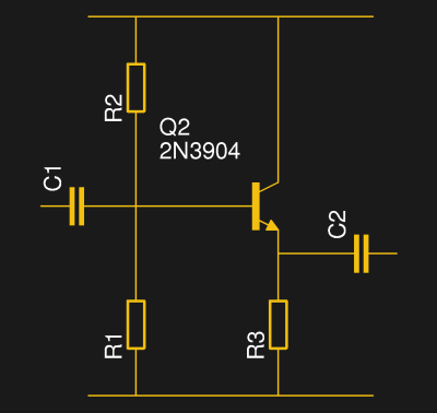
The emitter follower circuit

Just as the common emitter amplifier and common base amplifier each tied those respective transistor terminals to a fixed potential and used the other two terminals as amplifier input and output, so does the common collector circuit. The base forms the input and its bias circuit is identical to that of the common emitter amplifier, but the rest of the circuit differs in that the collector is tied to the positive rail, the emitter forms the output, and there is a load resistor to ground in the emitter circuit.

As with both of the other configurations, the bias is set such that the transistor is turned on and passing a constant current that keeps it in its region of an almost linear relationship between small base current changes and larger collector current changes. With variation of the incoming signal and thus the  base current there is a corresponding change in the collector current dictated by the transistor’s gain, and thus an output voltage is generated across the emitter resistor. Unlike the common emitter amplifier this voltage increases or decreases in step with the input voltage, so the emitter follower is not an inverting amplifier.

Continue reading “Biasing That Transistor: The Emitter Follower”

Cams And Pushrods Improve 3D-Printed Compressed Air Engine

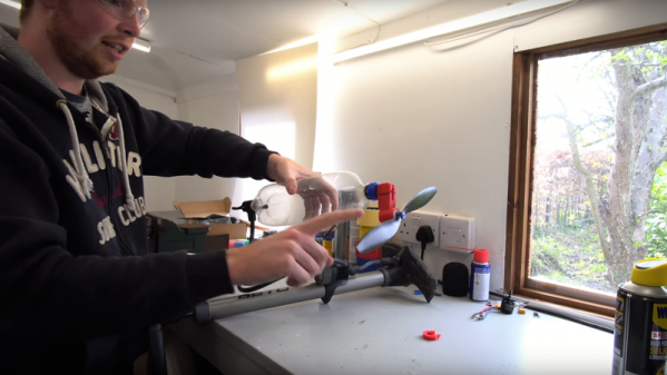
Some folks just can’t leave well enough alone, and that often ends up being a good thing. Such is the case with this 3D-printed compressed air engine, which just keeps getting better.

The design has changed a lot since we first covered [Tom Stanton]’s attempts at reviving the powerplant from the glory days of the Air Hogs line of toys, which he subsequently built a plane around. The engine was simple, with a ball valve that admitted air into the cylinder when a spring mounted to the top of the piston popped it out of the way. That spring has always bothered [Tom], though, compelling him to go back to the drawing board. He wanted to replace the ball valve with one actuated by a cam and pushrod. This would increase the complexity of the engine quite a bit, but with the benefit of eliminating the fail point of the spring. With a few iterations in the design, he was able to relocate the ball valve, add a cam to the crankshaft, and use a pushrod to open the valve. The new design works much better than the previous version, sounding more like a lawnmower than a 3D-printed engine should. Check out the design process and some tests in the video below.

And speaking of lawnmowers that run on compressed air

Continue reading “Cams And Pushrods Improve 3D-Printed Compressed Air Engine”

A Mechanical Laser Show With 3D-Printed Cams And Gears

Everyone knows how to make a POV laser display — low-mass, first-surface mirrors for the X- and Y-axes mounted on galvanometers driven rapidly to trace out the pattern. [Evan Stanford] found a simpler way, though: a completely mechanical laser show from 3D-printed parts.

The first 10 seconds of the video below completely explains how [Evan] accomplished this build. A pair of custom cams wiggles the laser pointer through the correct sequences of coordinates to trace the desired pattern out when cranked by hand through a 1:5 ratio gear train. But what’s simple in concept is a bit more complicated to reduce to practice, as [Evan] amply demonstrates by walking us through the math he used to transfer display shapes to cam profiles. If you can’t follow the math, no worries — [Evan] has included all the profiles in his Thingiverse collection, and being a hand model software guy by nature, he’s thoughtfully developed a program to automate the creation of cam profiles for new shapes. It’s all pretty slick.

Looking for more laser POV goodness? Perhaps a nice game of laser Asteroids would suit you.

Continue reading “A Mechanical Laser Show With 3D-Printed Cams And Gears”