[Chonggang Li] wrote in to share a link to the final project he and [Ran Hu] built for their embedded systems class. It’s called Piano Hero and uses an FPGA to implement a camera-based touch screen system.
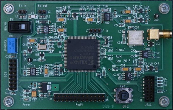
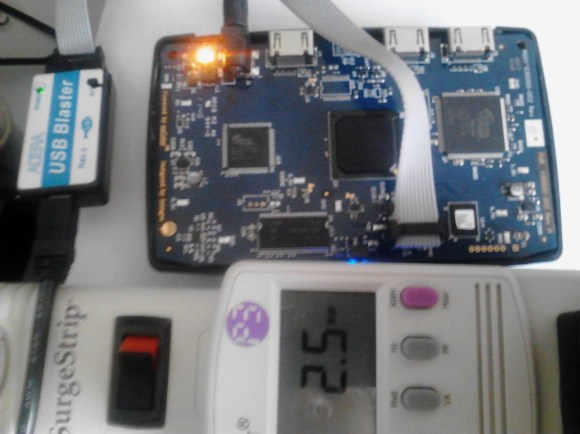
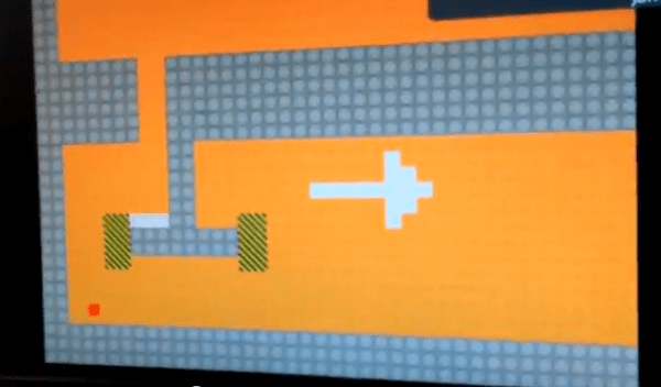
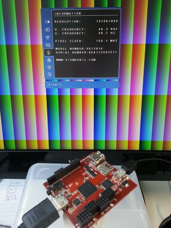
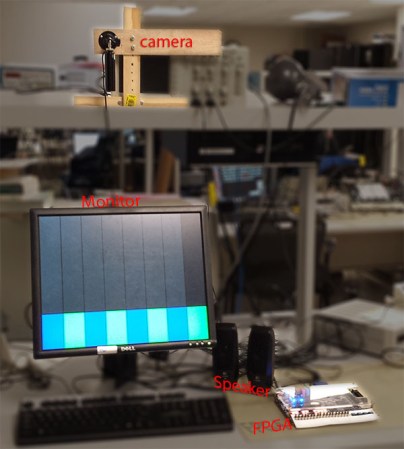
All of the hardware used in the project is shown above. The monitor acts as the keyboard, using an image produced by the FPGA board to mark the locations of each virtual key. It uses a regular VGA monitor so they needed to find some way to monitor touch inputs. The solution uses a camera mounted above the screen at an obtuse angle. That is to say, the screen is tilted back just a bit which allows the images on it to be seen by the camera. The FPGA board processes the incoming image, registering a key press when your finger passes between the monitor and the camera. This technique limits the input to just a single row of keys.
This should be much simpler than using a CCD scanner sensor, but that one can track two-dimensions of touch input.
Continue reading “Camera-based Touchscreen Input Via An FPGA”