![]()
Laser cutter owners may find this online box design tool which [Jon] built quite useful. It’s got a few more joint options than the Inkscape box design add-on does.
Apparently the US Navy has the ability to bring down drones in a flaming pile of laser-caused death. [Thanks Joshua]
[Michail] has been working on a transistor-based full adder. He’s posted a Spice simulation if you want to learn about the design.
Turn your crystal clear LED bodies into diffuse ones using a wooden dowel, power drill, and sandpaper. The results look better than what we’ve accomplished by hand. [Thanks Vinnie]
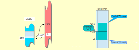
Play your favorite Atari Jaguar games on an FPGA thanks to the work [Gregory Estrade] did to get it running on a Stratix-II board. You can pick up the VHDL and support tools in his repo. If you’re just curious you can watch his demo vid.
Members of Open Space Aarhus — a hackerspace in Risskov, Denmark — have been playing around with a bunch of old server fans. They made a skirtless hovercraft by taping them together and letting them rip. Too bad it can’t carry its own power supply
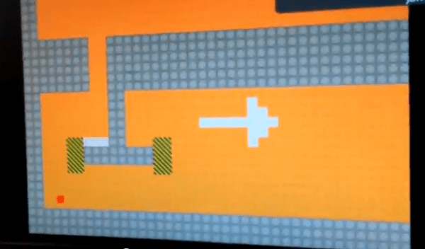
Here’s another final project from that bountiful Cornell embedded systems class. This team of students made a maze game that forms the maze by capturing walls drawn on a white board.
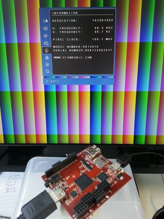
And finally, here’s a unique chess board you can build by raiding your parts bin. [Tetris Monkey] made the board from the LCD screen of a broken monitor. The playing pieces are salvaged electronics (like big capacitors) against corroded hardware (like nuts and bolts). We think it came out just great!