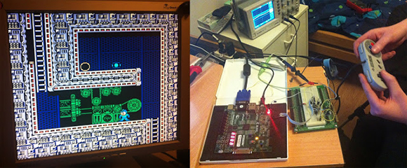
When the developer of the µTorrent torrent client and the ScummVM LucasArts adventure game interpreter gets bored, something cool is bound to happen. Luckily for us, [Ludde] was a bit listless over Christmas, and with more time than energy to burn, implemented a Nintendo Entertainment System on an FPGA dev board.
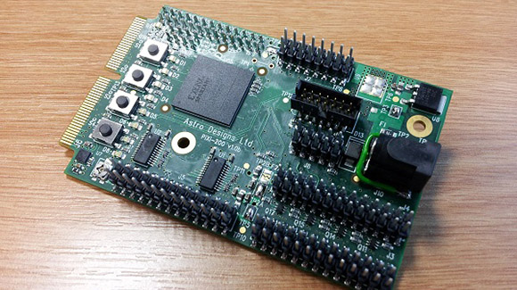
The NES was powered by a Ricoh 2A03 CPU, a chip nearly identical to the 6502 found in the Commodore 64s and Apple IIs of the early 1980s. There are a few differences between the two, though: the NES CPU includes an Audio Processing Unit on the chip and is connected to a very cool Picture Processing unit elsewhere on the NES. [Ludde] put all these chips in his Spartan-6 FPGA with a lot of Verilog code.
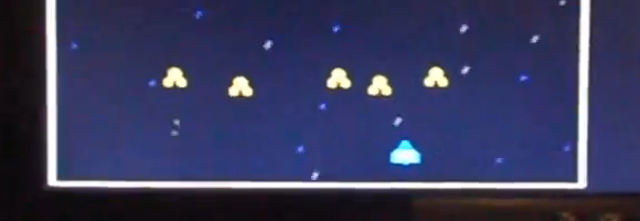
The rest of the system – the RAM, display output, and controller input comes from the peripherals attached to the FPGA dev board. [Ludde]’s specific board didn’t have a good digital to analog converter, so the composite output was traded for a VGA output. It’s not a completely accurate color pallet, but it’s still an amazing piece of work for someone who was simply bored.
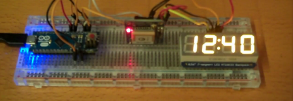
 [James] doesn’t need a circuit board or even some protoboard to get the job done.