Reading An N64 Controller With A Microcontroller

We’ve seen NES, SNES, Sega, and just about every weird controller Atari put out connected to microcontrollers, but connecting the N64 controller to a project has remained one of those seldom-seen, rarely copied endeavors, not often tackled by makers around the globe. [Pieter-Jan] decided to throw his hat in the ring and give reading an N64 controller with a PIC a try, and we’re pleased to report he’s been completely successful.

One of the difficulties of reading an N64 controller is simply the speeds involved; with only three pins on the controller port, the N64 controller uses a serial protocol to send 32 bits of controller data at a fairly fast rate. Armed with a PIC18F ‘micro, [Pieter] realized that programming in C would be too slow, he needed to go all the way down to the bare metal and program his micro in assembly.

Every time the N64 controller data needs to be read, the console sends out a 9-bit polling request. The controller responds in turn with a 32-bit sequence informing the console of the status of all the buttons and joysticks. Once [Pieter] got his micro sending the correct polling response, it was only an issue of parsing the data returned from the controller.

Right now, [Pieter] has a small demo board rigged up that flashes a LED whenever the A, B, or Z buttons are pressed. This can be expanded to the remaining buttons and joystick, but for now we’ll just enjoy [Pieter]’s demo after the break.

Continue reading “Reading An N64 Controller With A Microcontroller”

Tiny OLED Oscilloscope Gets A Fancy Case

[Gabriel Anzziani] has just unleashed a newer, more convenient version of his Xprotolab portable oscilloscope, logic analyzer, and function generator. It’s up on Kickstarter, and the price is actually very nice for a tool of this caliber.

We first saw the Xprotolab early last year and ran into [Gabriel] at this year’s World Maker Faire in New York. On both occasions we were impressed with the size and capability of this very, very small OLED-display oscilloscope and general breadboarding Swiss army knife.

The Xprotolab features a two-channel, 200 kHz oscilloscope, 8-input logic analyzer, and an arbitrary waveform generator that should be good enough for all your breadboarding adventures. On top of that, the Xprotolab can sniff SPI, I2C, and UART protocols, and even has a small spectrum analyzer tucked away in a device small enough to lose in your pocket.

The updated-for-Kickstarter Xprotolab features an enclosure with a LiPo battery good for 12 hours of use per charge. Sure, it’s not a bench full of old HP and Tektronix gear, but for the budding maker, this seems like a very useful tool indeed.

Directing An Alarm System Straight To The Internet

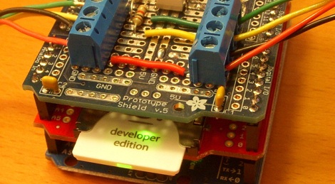
[Scott] has a pretty nice alarm system at his house – it will give the operator at his alarm company enough information to determine if it’s a fire alarm, burglary, or just a cat walking in front of a sensor. [Scott] wanted to cut out the middle man and receive notifications from his alarm system on his phone. He did just that, with the help of a trusty Arduino and the very cool Electric Imp.

[Scott]’s build began with an Arduino attach to a Raspi to monitor state changes in the alarm system. Because the designers of the alarm system included a very helpful four-wire bus between the alarm panels and the part connected to the phone line, [Scott] found it fairly easy to tap into these lines and read the current alarm status.

Dedicating a Raspberry Pi to the simple task of polling a few pins and sending data out over WiFi is a bit overkill, so [Scott] picked up an Electric Imp Arduino shield to transmit data over WiFi. We’ve played around with the Imp before, and [Scott] would be hard pressed to come up with a cleaner solution to putting his alarm monitor on the Internet.

Now [Scott] has a very tidy alarm monitor that sends updates straight to his cell phone, no middle man required. A very neat build, and an excellent use of a very cool WiFi device.

Storing User Data On Your FPGA

We’ve seen FPGAs used to recreate everything from classic arcade games to ancient computers, but with each of these builds a common problem arises. Once you’ve got the hardware emulated on an FPGA, you’ve also got to get the ROMs into the project as well. In a very interesting hack, [Mike] figured out that the serial Flash chip that stores the FPGA settings has a lot of space free, so why not store user data there?

[Mike] got the idea from seeing a recreation of the classic BombJack arcade game we featured last month. In that build, [Alex] needed to store 112Kb of game data stored in 16 ROM chips. Unfortunately, [Alex]’s FPGA only had space for 40Kb of data. After realizing his FPGA had a 512Kb SRAM chip, [Alex] decided to put all the sprites, sounds, and levels of BombJack in the SRAM.

Impressed with [Alex]’s build, [Mike] set to work generalizing the hack to work with other projects. [Mike] notes that only a few FPGA boards are capable of storing user data next to the  configuration bitstream; the hack is impossible on the Digilent Basys2 board, but it works wonderfully on a Papilio One 250K.

As a very cool build that makes FPGA-related builds even easier, we’ve got to tip our hat to [Mike] for writing up a great tutorial.

Weird Processing Unit Only Has 4 Instructions

[Tomáš], a.k.a. [Frooxius] is playing around with computational theory and processor architectures – a strange hobby in itself, we know – and has created the strangest CPU we’ve ever seen described.

The Weird Processing Unit, or WPU, isn’t designed like the Intel or ARM CPU in your laptop or phone. No, the WPU is a thought experiment in computer design that’s something between being weird for the sake of being weird and throwing stuff at the wall and seeing what sticks.

The WPU only has four instructions, or attoinstructions, to change the state of one of the 64 pins on the computer – set to logical 1, set to logical 0, invert current state, and halt. These instructions are coded with two bits, and the operand (i.e. the wire connected to the computer) is encoded in another six bits.

These 64 wires are divided up into several busses – eight bit address and control busses make up the lowest 16 bits, a 32-bit data bus has a function akin to a register, and a 16-bit ‘Quick aJump bus’ provides the program counter and attocode memory. The highest bit on the WPU is a ‘jump bit’, implemented for unconditional jumps in code.

We’re not even sure the WPU can even be considered a computer. We realize, though, that’s probably not the point; [Tomáš] simply created the WPU to do something out of the ordinary. It’s not meant to be a real, or even useful, CPU; it’s simply a thought experiment to see what is possible by twiddling bits around.

Tip ‘o the hat to [Adam] for sending this one in.

LiPo Powered Stellaris Launchpad

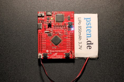
Want mobile power for your Stellaris Launchpad development board? [Philipp] was looking to add some lithium power for the Launchpad. He used an off the shelf single cell LiPo battery and connected it to the 5V rail of the Launchpad board. It didn’t work.

So [Philipp] started looking through the schematics and noticed that the regulator was working fine, but the Stellaris wasn’t starting up. He tracked down a voltage supervisor connected to the Stellaris reset pin. After some investigation, it was clear that this supervisor was holding the device in reset.

The solution is a quick and dirty hack: cut the trace that connects the reset line to the voltage line. With this modification, the device starts up from the LiPo without any issues. [Philipp] does note that you should be careful about battery under-voltage and over-voltage. This hack doesn’t handle charging the LiPo battery, but we’ve discussed that in the past.

Magic Finger Input Device Is A Camera On Your Finger Tip

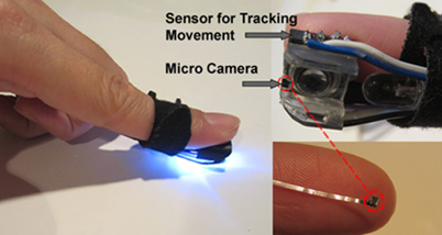
What if we could do away with mice and just wear a thimble as a control interface? That’s the concept behind Magic Finger. It adds as movement tracking sensor and RGB camera to your fingertip.

Touch screens are great, but what if you want to use any surface as an input? Then you grab the simplest of today’s standard inputs: a computer mouse. But take that one step further and think of the possibilities of using the mouse as a graphic input device in addition to a positional sensor. This concept allows Magic Finger to distinguish between many different materials. It knows the difference between your desk and a piece of paper. Furthermore, it opens the door to data transfer through a code scheme they call a micro matrix. It’s like a super small QR code which is read by the camera in the device.

The concept video found after the break shows off a lot of cool tricks used by the device. Our favorite is the tablet PC controlled by moving your finger on the back side of the device, instead of interrupting your line of sight and leaving fingerprints by touching the screen.

Continue reading “Magic Finger Input Device Is A Camera On Your Finger Tip”