For both the Raspberry Pi and BeagleBone Black, there’s a lot of GPIO access that happens the way normal Unix systems do – by moving files around. Yes, for most applications you really don’t need incredibly fast GPIO, but for the one time in a thousand you do, poking around /sysfs just won’t do.
[Chirag] was playing around with a BeagleBone and a quadrature encoder and found the usual methods of poking and prodding pins just wasn’t working. By connecting his scope to a pin that was toggled on and off with /sysfs he found – to his horror – the maximum speed of the BBB’s GPIO was around three and a half kilohertz. Something had to be done.
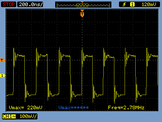
After finding an old Stack Overflow question, [Chirag] hit upon the solution of using /dev/mem to toggle his pins. A quick check with the scope revealed he was now toggling pins at 2.8 Megahertz, or just about a thousand times faster than before.