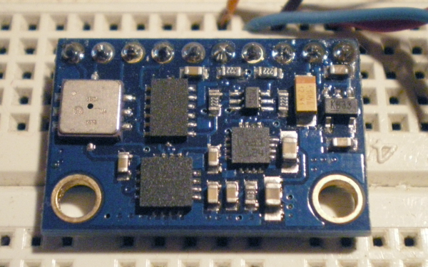
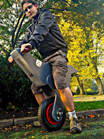
Self Balancing Robot Uses Cascading PID Algorithms

At this point we’re beginning to think that building a self-balancing robot is one of the rights of passage alongside blinking some LEDs and writing Hello World on an LCD screen. We’re not saying it’s easy to pull off a build like this one. But the project makes you learn a lot about a wide range of topics, and really pushes your skills to the next level. This latest offering comes from [Sebastian Nilsson]. He used three different microcontrollers to get the two-wheeler to stand on its own.

He used our favorite quick-fabrication materials of threaded rod and acrylic. The body is much taller than what we’re used to seeing and to help guard against the inevitable fall he used some foam packing material to protect the top level. Three different Arduino boards are working together. One monitors the speed and direction of each wheel. Another monitors the IMU board for position and motion feedback, and the final board combines data from the others and takes care of the balancing. Two PID algorithms provide predictive correction, first by analyzing the wheel motion, then feeding that data into the second which uses the IMU feedback. It balances very well, and can even be jostled without falling. See for yourself in the clip after the break.

Continue reading “Self Balancing Robot Uses Cascading PID Algorithms”

LayerOne Badge Hacking Twofer

Here’s a pair of LayerOne Badge hacks that actually included the RC as intended by the badge designers.

First up, we have the autonomous RC car built by [Arko]. He calls it Stanley Jr. as an homage to the Stanford DARPA Grand Challenge vehicle. It uses an Arduino shield to add a servo with an ultrasonic rangefinder on it. The lets the vehicle drive a bit, stop and scan the horizon, then drive some more. The hope is the rangefinder will keep it from running into anything. There’s a quick test run embedded after the break.

On the right is the badge hack which [Zjpahle] finished up after the contest was already over. He also chose to go with an Arduino shield, this time it’s an IMU board. But he added a standalone Arduino board to the vehicle which drives some EL wire (ground effects) and adds IR sensors to the front of the car. The IR sensors are for obstacle avoidance, and the IMU lets him tilt his badge for direction control.

We looked at the winner of the badge hacking competition on Wednesday. That hack didn’t involve the car, but used the badge as a Morse Code beacon.

Continue reading “LayerOne Badge Hacking Twofer”

Modeling An Object With Internal IMUs

[Joseph Malloch] sent in a really cool video of him modeling a piece of foam twisting and turning in 3D space.

To translate the twists, bends, and turns of his piece of foam, [Joseph] used several inertial measurement units (IMUs) to track the shape of a deformable object. These IMUs consist of a 3-axis accelerometer, 3-axis gyroscope, and a 3-axis magnetometer to track their movement in 3D space. When these IMUs are placed along a deformable object, the data can be downloaded from a computer and the object can be reconstructed in virtual space.

This project comes from the fruitful minds at the Input Devices and Music Interaction Lab at McGill University in Montreal. While we’re not quite sure how modeled deformable objects could be used in a user interface, what use is a newborn baby? If you’ve got an idea of what this could be used for, drop a note in the comments. Maybe the Power Glove needs an update – an IMU-enabled jumpsuit that would put the Kinect to shame.

Continue reading “Modeling An Object With Internal IMUs”

Climbing The Mountain Of Quadcopter Design

What a sweet thing it is to see the first outdoor flight of a quadcopter. [Botched] has done a wonderful job of documenting the entire build process. Take a look at all that he has done, then jump after the break to see the extremely stable test flight footage.

Earlier iterations used feedback electronics that he designed, etched, and soldered himself. We think they looked pretty good, but he was not happy with the performance. He spent a bunch of time redesigning the IMU board, but after he printed out the PCB artwork he decided his soldering was not up to the QFN challenge and he went with a pre-assembled breakout board.

His post about PID tuning is quite interesting. He removed two of the motors and mounted those opposite ends of the chassis to a hinged stand. This let him tweak the feedback loop until the two remaining propellers were able to maintain balance even when he nudged the unit.

His test flight footage is accompanied by an on-board camera shot. He simply taped a smart phone to the battery and let it roll. Make sure you turn off your speakers before watching this one or the motor noise will let the boss know you’re reading Hackaday again instead of working.

Continue reading “Climbing The Mountain Of Quadcopter Design”

Short And Squat Balancing Bot Is Extremely Stable

[Lauszus] really put together an impressive self balancing robot platform. It is virtually motionless when balancing in place, and that stability is never lost even when motoring across the room.

Part of the success behind this build is the use of quality components. He’s got a really nice set of motors with built-in encoders which give feedback to the balancing system. They work in conjunction with a gyroscopic sensor and PID code to keep the two-wheeled platform upright. An mbed board running 96 MHz provides plenty of computing power for the balancing system. But an Arduino can also be found on board. This was included to facilitate Bluetooth connectivity with the remote control as [Lauszus] didn’t want to port the code he had already written.

The fourteen minute video after the break shares the details behind how the PID controller is tuned and how [Lauszus] implements target angle and a few other factors. Of course he talks about the hardware choices, and demonstrates functionality by driving the bot around using a wireless PS3 controller.

The construction method which uses masonite strips and threaded rod does a good job of protecting the hardware mounted on it. We’re always a bit worried about these bots falling over and some of the projects we see offer little or no protection. Once thing that helps protect against a spill is a piezo buzzer which sounds when the battery is getting low.

Continue reading “Short And Squat Balancing Bot Is Extremely Stable”

Quadcopter Stabilization System Using Wii Motion Plus

If you’re contemplating a quadcopter build here’s a way to add stabilization hardware without breaking the bank. The BaronPilot project uses an Arduino and a Wii Motion Plus module to ensure an even keel for your flying projects. The hardware inside of the Motion Plus includes two gyroscopes, which the BaronPilot monitors for changes in your flying rig’s orientation. The project serves as a co-pilot by differentiating between movements caused by the remote control, and changes due to wind or other outside factors (like hitting the quadcopter with a stick as seen in the video after the break). It should all translate to less chance of crashing due to operator error.

You can pick up a Motion Plus for less than twenty dollars, a deal when compared to the IMU boards that we usually see in quadcopter builds which usually run more than twice that amount. It’s an I2C device which makes it easy to hook up to just about anything. This project has native support for Teensy, Arduino Nano, and Arduino clones using an ATmega328 chip. But the portability of the Arduino platform should make it easy to tweak the code for use with just about any microprocessor.

Continue reading “Quadcopter Stabilization System Using Wii Motion Plus”

One Really Big Quadcopter That Is Following In The Steps Of The Spruce Goose

Behold the Land-Bear-Shark, a quadcopter on a rather grand scale. At a full eight kilograms it’s an easy target to compare the [Howard Hughes] behemoth, but in addition to the weight, this still has yet to make its first flight.

To give you some scale to the image above, the board at the center is an Arduino. It controls the beast, along with the help of a SparkFun IMU board which rides atop. Really, if any quadcopter of this size has a chance of working, this should be the one. The construction is beautiful, making use of carbon fiber rod along with 3D-printed connectors to assemble the frame. A lot of thought has gone into small things like conserving weight used on the landing gear, which are incorporated into the bottom corner brackets. The batteries are connected in a manner that makes them easy to adjust, acting as ballast for balancing the craft.

We’re keeping our fingers crossed that this will be more than the tongue-in-cheek title of the post which calls it a Quadrotor-shaped sculpture.

[via Adafruit]