Little Hex Tricks Make Little Displays A Little Easier

Depending on the device in hand and one’s temperament, bringing up a new part can be a frolic through the verdant fields of discovery or an endless slog through the grey marshes of defeat. One of the reasons we find ourselves sticking with tried and true parts we know well is that interminable process of configuration. Once a new display controller is mostly working, writing convenience functions to make it easier to use can be very satisfying, but the very first thing is figuring out how to make it do anything at all. Friend of Hackaday [Dan Hienzsch] put together a post describing how to use a particular LED controller which serves as a nice walkthrough of figuring out the right bitmath to make things work, and includes a neat trick or two.

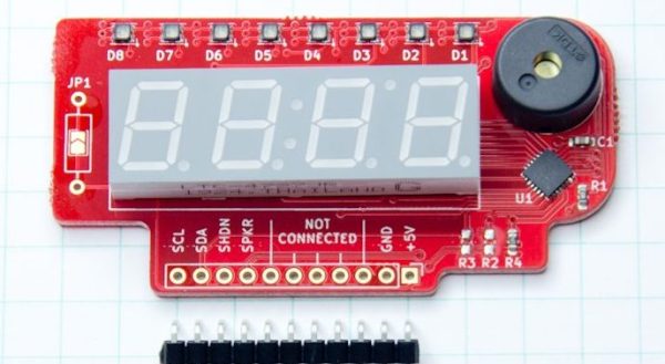
The bulk of the post is dedicated to describing the way [Dan] went about putting together his libraries for a 7-segment display demo board he makes. At its heart the board uses the IS31FL3728 matrix driver from ISSI. We love these ISSI LED controllers because they give you many channels of control for relatively low cost, but even with their relative simplicity you still need to do some bit twiddling to light the diodes you need. [Dan]’s post talks about some strategies for making this easier like preconfigured lookup tables with convenient offsets and masking bits to control RGB LEDs.

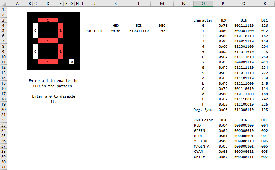
There’s one more trick which we think is the hidden star of the show; a spreadsheet which calculates register values based on “GUI” input! Computing the bit math required to control a display can be an exercise in frustration, especially if the logical display doesn’t fit conveniently in the physical register map of the controller. A spreadsheet like this may not be particularly sexy but it gets the job done; exactly the kind of hack we’re huge fans of here. We’ve mirrored the spreadsheet so you can peek at the formulas inside, and the original Excel document is available on his blog.

Tiny LED Cube Packs Six Meters Of Madness

When [Freddie] was faced with the challenge of building a sendoff gift for an an LED-loving coworker he hatched a plan. Instead of making a display from existing video wall LED panels he would make a cube. But not just any cube, a miniature desk sized one that wasn’t short of features or performance. We’d be over the moon if someone gifted us with this itty-bitty Qi coil-powered masterpiece of an RGB cube.

Recently we’ve been blessed with a bevy of beautiful, animated RGB cubes but none hit quite this intersection of size and function. The key ingredient here is tiny but affordable RGB LEDs which measure 1 mm on a side. But LEDs this small are dwarfed by the otherwise minuscule “2020” package WS2812’s and APA102s of the world. Pushing his layout capabilities to the max [Freddie] squeezed each package together into a grid with elements separated by less than 1 mm, resulting in a 64 LED panel that is only 16 mm x 16 mm panel (with test points and controller mounted to the back). Each of these four-layer PCBs that makes up the completed cube contains an astonishing 950 mm of tracking, meaning the entire cube has nearly six meters of traces!

How do you power such a small device with no obvious places to locate a connector? By running magnet wire through a corner and down to a Qi coil of course. Not to let the cube itself outshine the power supply [Freddie] managed to deadbug a suitably impressive supply on the back of the coil itself. Notice the grain of rice in the photo to the left! The only downside here is that the processor – which hangs diagonally in the cube on a tiny motherboard – cannot be reprogrammed. Hopefully future versions will run programming lines out as well.

Check out the video of the cube in action after the break, and the linked photo album for much higher resolution macro photos of the build. While you’re there take a moment to admire the layout sample from one of the panels! If this sets the tone, we’re hoping to see more of [Freddie]’s going-away hacks in the future!

Continue reading “Tiny LED Cube Packs Six Meters Of Madness”

Automating The Design Of Word Clocks

Word clocks, or a matrix of light-up letters that spell out the time, are a standard build for all enterprising electronics enthusiasts. The trouble is finding the right way to drive a matrix of LEDs and the significant amount of brainpower that goes into creating a matrix of letters that will spell out the time without making it look like it’s supposed to spell out the time.

For his Hackaday Prize entry this year, [Stephen Legge] is creating a standard toolkit that makes word clocks easier to build. It’s a hardware and software project, allowing for LED matrices of any reasonable size, and the software to make a grid of letters that only spells out the words you want and not the four-letter ones you don’t.

The hardware for this project is built around the IS31FL3733 LED driver from ISSI. This is an interesting chip that takes I2C in and spits out a LED matrix with very few additional support components. This chip provides [Stephen] with a 12×16 single-color LED matrix, which is more than enough for a word clock.

Where this build gets slightly more interesting is the creation of a custom matrix of letters that will still spell out ‘quarter to noon’ when lit in the appropriate way. This is a big challenge in creating a customized word clock; you could always borrow the layout of the letters from another word clock, but if you want customized phrases, you’ll either have to sit down with a pencil and graph paper, or write some software to do it automatically.

It’s a great project, and since all of [Stephen]’s work is being released under Open Source licenses, it’s a great entry to the first portion of the Hackaday Prize where we’re challenging hardware creators to build Open Hardware.

New Part Day: I2C In, Charlieplexed LEDs Out

It seems that most of the electrical engineering covered on Hackaday concerns exactly one problem domain: how to blink a bunch of LEDs furiously. There are plenty of LED drivers out there, but one of the more interesting in recent memory came from ISSI in the form of a chip that turns I2C into a Charlieplexed LED array. You may have seen this chip — the IS31FL3731 — in the form of an Adafruit LED matrix and some stupid thing some idiot made, but with it you’re only ever going to get 144 LEDs in an array, not enough if you want real blinky bling.

Now ISSI has released a more capable chip that turns I2C into many more Charlieplexed LEDs. The IS31FL3741 will drive up to 351 LEDs in a 39×9 matrix, or if you’re really clever, an 18×18 single color LED matrix.

Features of this chip include reverse/short detection for each individual LED, 8-bit PWM, dimming functions, a de-ghosting feature that guarantees a LED is either on or off, a configurable row/column matrix, and a few other handy tools that you would like to see in a LED matrix driver chip. The most impressive chip in this series will be available for under $2/piece in quantities of 2500, although unlike the IS31FL3731, it appears this new chip will only be available in a QFN package.

Speaking from experience, this is a really great chip for driving a whole boatload of LEDs, provided you have a pick and place machine. Yes, you can hand-solder a QFN and several hundred 0402 LEDs, but I wouldn’t recommend it. I really, really wouldn’t recommend it. That said, this is the perfect chip for maximum blinky bling, and the press material from ISSI gives us the great idea of using one of these chips as the backlight controller for RGB LED mechanical keyboards. That’s a great application, and the chip is pretty cheap, too.

You can check out ISSI’s blinky demo video of this chip below.

Continue reading “New Part Day: I2C In, Charlieplexed LEDs Out”