Feel The Force With A Pocket Magnetometer

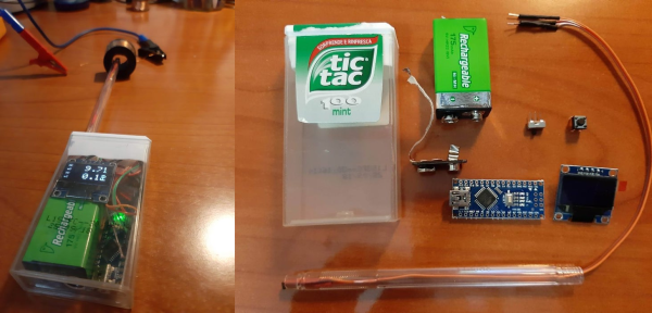
With the rise of affordable 3D printers, we just don’t see the projects in Tic Tac boxes that we used to. That’s kind of a shame. Not only are you upcycling existing plastic when you use one, they’re decently sized component vessels for pocket builds such as [rgco]’s portable magnetometer, especially if you can get the 100-count box. Best of all, they’re see-through!

Sure, you could get a magnetometer app for your phone to test out the strength of your Buckyballs, but this is more fun, and you can use it in more places. This build doesn’t take much — an Arduino Nano reads from a Hall effect sensor and outputs the magnetic flux density in militeslas (mT) on an OLED. Fortifying the sensor by mounting it inside the body of an old (also see-through!) ballpoint pen body is a nice touch.

In order to calibrate it, [rgco] made a solenoid by wrapping a length of PVC with magnet wire. The code for this very portable and low-cost magnetometer measures the magnetic field 2000 times in under three-tenths of a second, and outputs both the mean and the standard deviation of these measurements.

Magnetometers can ID all kinds of things from submarines to Suburbans. Here’s an ESP8266 magnetometer that opens a driveway gate when it detects the car.

Little Hex Tricks Make Little Displays A Little Easier

Depending on the device in hand and one’s temperament, bringing up a new part can be a frolic through the verdant fields of discovery or an endless slog through the grey marshes of defeat. One of the reasons we find ourselves sticking with tried and true parts we know well is that interminable process of configuration. Once a new display controller is mostly working, writing convenience functions to make it easier to use can be very satisfying, but the very first thing is figuring out how to make it do anything at all. Friend of Hackaday [Dan Hienzsch] put together a post describing how to use a particular LED controller which serves as a nice walkthrough of figuring out the right bitmath to make things work, and includes a neat trick or two.

The bulk of the post is dedicated to describing the way [Dan] went about putting together his libraries for a 7-segment display demo board he makes. At its heart the board uses the IS31FL3728 matrix driver from ISSI. We love these ISSI LED controllers because they give you many channels of control for relatively low cost, but even with their relative simplicity you still need to do some bit twiddling to light the diodes you need. [Dan]’s post talks about some strategies for making this easier like preconfigured lookup tables with convenient offsets and masking bits to control RGB LEDs.

There’s one more trick which we think is the hidden star of the show; a spreadsheet which calculates register values based on “GUI” input! Computing the bit math required to control a display can be an exercise in frustration, especially if the logical display doesn’t fit conveniently in the physical register map of the controller. A spreadsheet like this may not be particularly sexy but it gets the job done; exactly the kind of hack we’re huge fans of here. We’ve mirrored the spreadsheet so you can peek at the formulas inside, and the original Excel document is available on his blog.

Robo Pony Greets Hackerspace Visitors

Robotic animal companions were once all the rage, though their limited personalities and annoying sound effects often relegated them to the bin fairly quickly. This makes them all the more ripe for hacking. [David Bynoe] had a Baby Butterscotch that was in need of a new home, and he decided to put the pony to work at his local hackerspace.

The Baby Butterscotch pony is a charming beast in stock form, yet highly menacing once its skin is removed. Mounted to a plaque, the pony has three PIR sensors that detect movement. These sensors are used to allow the pony to act as a door greeter, waking up when people enter the hackerspace and following them around the room. The additional hardware interfaces with the pony’s stock electronics by using floating capacitors and relays to activate the original capacitive touch sensors. The final piece is finished with a coat of gold paint and some RGB eyes to complete the look.

It’s a fun project that gives Vancouver Hack Space a little personality, and we’re sure it’s enjoyed by the members. We’ve seen other companion toy hacks before, with the Furby always being a ripe target for projects. Video after the break.

Continue reading “Robo Pony Greets Hackerspace Visitors”

Broken 3D Printer Turned Scanning Microscope

A few years ago, [Wayne] managed to blow out the main board of his Flashforge Finder attempting to change the fan. But the death of one tool ended up being the birth of another, as he ended up using its mechanical components and a Raspberry Pi to create an impressive scanning microscope.

Scan of Ulysses S. Grant from a US $50 bill

As you might have guessed from the name, the idea here is to scan across the object with a digital microscope to create an enlarged image of the entire thing. This requires some very precise control over the microscope, which just so happens to be exactly what 3D printers are good at. All [Wayne] had to do was remove the hotend, and print some adapter pieces which let him mount a USB microscope in its place.

The rest is in the software. The Raspberry Pi directs the stepper motors to move the camera across the object to be scanned in the X and Y dimensions, collecting thousands of individual images along the way. Since the focus of the microscope is fixed and there might be height variations in the object, the Z stage is then lifted up a few microns and the scan is done again. Once the software has collected tens of thousands of images in this manner, it sorts through them to find the ones that are in focus and stitch them all together.

The process is slow, and [Wayne] admits its not the most efficient approach to the problem. But judging by the sample images on the Hackaday.io page, we’d say it gets the job done. In fact, looking at these high resolution scans of 3D objects has us wondering if we might need a similar gadget here at the Hackaday Command Bunker.

The project is actually an evolution of an earlier attempt that used gutted optical drives to move the microscope around.

An Eight-Day Home Automation Hackathon Is Inspiration For Getting More Projects Done

There’s nothing quite like a deadline to cut through extras and get right at the heart of the problem. Maybe we should all follow Interpreet’s example and stop thinking about automating our homes and just make it in an eight-day hackathon. His talk at the 2019 Hackaday Superconference covers the zero-to-deployment home automation build he finished in the eight days leading up to his move from one continent to another.

Hackaday’s very own Inderpreet Singh found himself pulling up roots and moving from his home in India to teach at Centennial College in Toronto, Canada. He needed a way to keep an eye on his home from afar and the name of the game is IoT. When the only choice is “whatever works right now”, you can learn a lot about simple solutions.

He chose familiar hardware to work with, with the ESP8266 making up the bulk of the nodes and a Raspberry Pi as as a central hub for the setup. He chose to communicate between all the nodes on his system using WiFi because the hardware is robust and available. With security in mind, he keeps the automation system separate from the daily use WiFi system by grabbing an extra access point to serve as the automation network. The Raspberry Pi serves as a router of sorts; its Ethernet port is connected to the IoT device’s AP, while the onboard WiFi is used to connect to the home’s main AP for a connection to the wider Internet.

Software for the system is built on a REST API served by a Python Flask app. Many would advocate for using MQTT but Inderpreet’s testing with that protocol came up short as the broker he intended to use was no longer available. One of the interesting parts of his system design is that all nodes will check in at regular intervals; this allows them to inquire about actions they need to take, but it also allows the system to detect a malfunctioning node immediately. I’ve seen a similar trick used by Elliot Williams where he assigns a “ping” topic to all MQTT devices that causes them to report in with their IP address. Having a system to query and ensure the health of every node is a big tip to take away from this talk.

Continue reading “An Eight-Day Home Automation Hackathon Is Inspiration For Getting More Projects Done”

New Part Day: LED Driver Is FPGA Dev Board In Disguise

Our new part of the day is the ColorLight 5A-75B, a board that’s meant to drive eight of those ubiquitous high-density color LED panels over gigabit Ethernet. If you were building a commercial LED wall, you’d screw a bunch of the LED panels together, daisy-chain a bunch of these boards to drive them, supply power, and you’d be done. Because of that high-volume application, these boards are inexpensive, around $15 each, and available as quickly as you can get stuff shipped from China.

But we’re not here to talk commercial applications. Managing fast Ethernet and pushing so many pixels in real time is a task best handled by an FPGA, and [Tom Verbeure] noticed that these things were essentially amazing FPGA development boards and started hacking on them. [q3k] put it up on GitHub, and you can follow along with the chubby75 reverse engineering project to dig into their secrets.

While the first generations of these boards used the old-standby Spartan 6, things got interesting for fans of open FPGA tools when newer versions were found using the Lattice ECP5-25 chips, the little brother of the stonking big chip [Sprite_TM] used on the 2019 Hackaday Supercon badge. If you want to grab one you’re looking for ColorLight boards marked with revision 6 or 7 as of this writing.

What does this mean? For the price of a gourmet hamburger, you get an FPGA that’s big enough to run a RISC-V softcore, two 166 MHz, 2 MB SDRAMS, flash for the FPGA bitstream, a bazillion digital outputs on 5 V level shifters, and two gigabit Ethernet ports. The JTAG port is broken out in 0.1″ headers, and it works with OpenOCD, which is ridiculously convenient. How’s that for a well-stocked budget FPGA dev board that’s served by a completely open toolchain? Continue reading “New Part Day: LED Driver Is FPGA Dev Board In Disguise”

Hackaday Podcast 051: Pointing With Your Tongue, C64 Touchpad, USB Killcord, And Audacity Does Everything

Hackaday editors Mike Szczys and Elliot Williams sort through the hacks you might have missed over the past seven days. In FPGA hacking news, there’s a ton of work being done on a newly discovered FPGA dev board. Kristina has a new column on input devices, kicking it off with tongue-actuated controllers. We wax philosophical about what data you need to backup and what you should let go. Plus Audacity is helping tune up CNC machines, copper tape is the prototyper’s friend, and fans of Open should take note of this laptop project.

Take a look at the links below if you want to follow along, and as always tell us what you think about this episode in the comments!

Take a look at the links below if you want to follow along, and as always, tell us what you think about this episode in the comments!

Direct download (60 MB or so.)

Continue reading “Hackaday Podcast 051: Pointing With Your Tongue, C64 Touchpad, USB Killcord, And Audacity Does Everything”