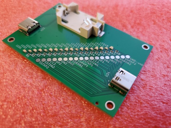
When USB first came on the scene, one of the benefits was that essentially any four conductors could get you to the point where you could send information at 12 Mbps. Of course everything is faster these days, and reaching today’s speeds requires a little bit more fidelity in the cables. This simple tester makes sure that your modern cables are actually up to the task.
One of the design goals of this project is to automate away the task of testing cables or finding one that works, especially before thinking a problem with a device is somewhere in software, spending hours or days debugging, before realizing that it’s actually being caused by a hardware malfunction. The small PCB has two USB-C fittings to plug in both of the ends of a cable to, and between those connectors there is a number of LEDs. Each LED is paired to one the many conductors within the USB cable, and not only does it show continuity of these conductors but it can also show a high resistance connection via a dimly-lit or off-color display from an LED.
One of the other interesting facets of this build is the use of JITX, which is a software-defined electronics CAD tool which allows PCB design to be automated by writing out the requirements of the PCB into code, rather than drawing it manually. It’s worth a look, and a lot of the schematics of this particular project as well as some discussion on this software can be found on the project’s GitHub page. Incidentally, if this tester looks familiar, it’s probably because your’re thinking of the open source hardware USB tester created by [Álvaro Prieto].


