Every magnet has a north and a south pole, but which is which? Sometimes it matters. If a product one builds features a magnetic closure or other part, the polarity of those magnets should be consistent in assembly. So how does one ensure they never glue a magnet wrong again? [Clough42] shows several ways to identify a magnet’s north and south poles using things many of us probably have ready at hand, and goes into a bit of theory while he’s at it.
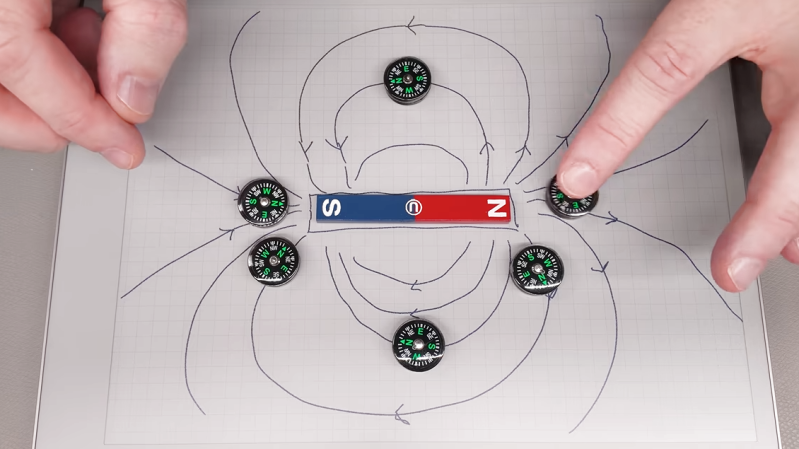
Probably the easiest way is to use a known-good and clearly labeled reference magnet. Same poles repel, and opposites attract. But if that’s not available, a simple magnetic compass can help. Because opposite poles attract, a compass’s north point will be attracted toward a magnet’s south pole, and vice versa.
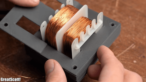
A Hall effect sensor, or an electromagnet — the winding and current flow determine the polarity — are other ways to measure a magnet’s poles. And here’s where [Clough42] dives into some details of how magnetic fields actually act, because it explains some seemingly strange behavior.
For example, at around 4:08 he demonstrates a Hall effect sensor board that is documented as lighting an LED when the south pole of a magnet is held to its front. It does that, but it also lights the LED when the north end of the magnet is held to the sensor’s back. That’s because the sensor isn’t actually directly sensing the magnet’s pole, it’s sensing the orientation of a magnetic field. The lesson is clear: make sure you’re measuring what you think you’re measuring. Near the end of the video he demonstrates a similar experience with a handy mobile phone app that senses magnetic fields by reading the device’s internal magnetic compass; by waving a strong magnet around, the detected polarity flips back and forth even though the magnet’s orientation isn’t changed.
So what does one do after positively identifying a magnet’s north and south poles? Label it clearly for use as a known-good reference magnet in the future is our suggestion. Watch the whole video below, then take a few minutes to dive into the nitty-gritty of what magnets actually are and how they work.
Continue reading “Ways To Empirically Identify A Magnet’s Polarity”