MSP430 Bit Banged USB 1.1

msp430-usb-hardware

Here’s a rather exciting development for those who work with MSP430 microcontrollers. [M-atthias] worked out a way to implement USB 1.1 on a MSP430G2452. He’s bit banging the communications as this hardware normally doesn’t support the Universal Serial Bus. This is much like using the V-USB stack for AVR micros.

The test hardware seen above uses an 18Mhz crystal to get the timings just right. As this squeezes the most out of the chip it should come as no surprise that the firmware is written in assembly. This is still quite early on in development but the core features are mostly there, having been implemented and debugged over several versions already. Currently the base functionality can be loaded using under 2k of flash memory. You can download the Mecrisp package from [M-atthias’] sourceforge page. If you want to lend a hand testing or developing it would be greatly appreciated.

[via 43oh blog]

Hackaday Links: November 29th, 2012

EMC2 CNC keyboard labels

If you’ve got a dedicated computer running EMC2 for CNC control you may be interested in these keyboard labels. [Rich] mentions that they use the labels for their engraver at the Connecticut Hackerspace. Just print them out and glue them in the face of the keys.

Dev board seminars and freebies

[Mike] wrote in to tell us STM is giving away samples of the STM32 F3 Discovery again. But you can also get in on some free seminars. One is an online webinar for TI’s Launchpad family, the other is for the F3 Discovery board and is being held all around the US.

Replacing batteries with USB power

[Johan] didn’t want to use batteries for the light on the microscope he uses when working with SMT parts. He added a few components with let him power the device from USB instead.

MSP430 VU meter uses FFT

Here’s an MSP430 using Fast Fourier Transform for signal processing. There’s very little explanation, but apparently this collection of FFT related material was used heavily in the project. [via Reddit]

Cell Racr

If you’re looking for a new office game you might consider Cell Racr. It pits your cellphone’s vibrating motor against everyone else’s. Just place the phone on an incline and repeatedly dial its number to advance toward the finish line.

Making A Touchless Vibrator With Reverse Engineering

Here’s one for the ladies (and men, we guess) out there.

[Beth] recently bought a LELO Lyla vibrator for herself, but found operating this wireless vibrator to be an exercise in mood-killing awkwardness. Wanting a more natural interface, she decided to reverse engineer a remote control vibrator. Here’s a cache; [Beth]’s blog has been up and down all day.

The LELO Lyla comes with a wireless control in the form of a neon pink remote. [Beth] thought this remote was a little clunky and felt like programming a VCR – something she doesn’t like in a sex toy. With the goal of improving this remote and allowing for a better user experience, [Beth] tore down this remote and began to build her own.

The new vibrator remote would have to be touchless – there’s nothing that kills the mood faster than mashing buttons. By using ultrasonic sensors, [Beth] would be able to control the intensity of her vibrator by simply waving her hand; a much more natural interface. With the control interface out of the way, the only thing left to do was to figure out how to control the business end of the vibrator.

The remote for a stock LELO Lyla comes with a MSP430 microcontroller and a 2.4 GHz CC2500 radio controlled over an SPI interface. Instead of disassembling the microcontroller and figuring out the firmware from scratch, [Beth] decided to sniff the SPI bus and make her own controller.

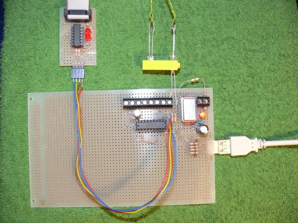
After attaching some 0.1″ headers to the stock remote and soldering a few wires to the microcontroller, [Beth] captured the SPI data with a Propeller dev board. By streaming the SPI traffic to a terminal, she was able to figure out exactly how the remote works and set out on building her own.

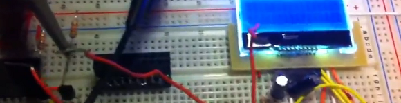
The new remote was built out of an Arduino Pro Mini, ultrasonic sensor, CC2500 radio and a four digit 7-segment display. After printing an enclosure, [Beth] had a very easy to use, hands free vibrator.

In the video after the break you can see [Beth]’s vibrator in action. She’s still looking for a few more ways to improve it such as predicting the movements of her hand with a phase-locked loop, but for now we’ll just tip our hat to [Beth] for a very awesome hack.

Continue reading “Making A Touchless Vibrator With Reverse Engineering”

MSP430 Launchpad Game Of Life Shield

[100uf] built an LED matrix shield for the MSP430 launchpad. His goal with this design was to have it play Conway’s Game of Life. It does just that, as you can see in the clip after the break. But it’s just waiting to learn some more tricks. After he tires of watching the cellular automaton he can try his hand at making some LED pendant animations.

As you can tell, the board was made in his home workshop. It’s not etched, but milled using the CNC machine shown in this image gallery. This is a single-sided PCB, which works well enough for the surface mount components and the downward facing pin sockets. But we wonder how difficult it was to solder the legs of that 8×8 LED matrix. It does have plastic feet at each corner that serve as standoffs to separate the body from the copper layer. But it still looks like a tight space into which he needed to get his iron and some solder.

Continue reading “MSP430 Launchpad Game Of Life Shield”

Turning The Hexbug Spider Into A Line-following Robot

[youtube=http://www.youtube.com/watch?v=quDHhuEsxEg&w=470]

You may be familiar with the Hexbug Spider, a small electronic robot toy sold at Target and Walmart for $20. While they’re able to be commanded to move forward, backward, and spin around on a dime, there aren’t any external sensors to make it really exciting. [Eric] sought to remedy this and came up with a line-following board replacement for the Hexbug Spider.

The stock Spider has a small circuit board that allows for the control of two motors with a remote. [Eric] removed this control board and replaced it with his own, powered by a TI MSP430 microcontroller. On this board, [Eric] included a pair of IR LEDs, able to detect the path of a white line drawn on the ground. With just a little bit of code, [Eric] made his $20 Hexbug Spider into a very cool looking robot.

[Eric] figured out how to improve his robot toy, but the power of the MSP430 microcontroller he used doesn’t limit him to only following lines. By using an MSP430 Launchpad, anyone can upload new code to the improved Spider, and even add new sensors to this creepy walking robotic toy.

Double-kettle Boiling Rig For And Easier Brew Day

[Dave] built a controller that lets him boil two kettles at once when brewing beer. The setup uses electric heating elements in each of the kettles. We prefer to use gas as it’s a bit easier to control temperature. But an electric system like this can be used inside during the winter months while propane is relegated to the outdoors. The other thing that immediately comes to mind is partial mash recipes that require steeping in one kettle, then sparging (rinsing off the grains) with water of a different temperature. That kind of thing is a snap since the two are controlled individually by the trimpots on the front of the control box.

Inside you’ll find two 220V solid state relays. The box itself plugs into the 220V outlet in his basement which is normally occupied by his clothes dryer cord. So as not to blow a fuse, the MSP430 chip driving the relays switches back and forth between them rather than turning both on at once. The system uses entirely manual control, but it should be an easy modification to add a thermocouple and PID algorithms if so desired.

After the break [Dave] shows off the system in a video clip.

Continue reading “Double-kettle Boiling Rig For And Easier Brew Day”

Oscilloscope VFD Repair Like Doing Brain Surgery On Yourself

[Jerry Pommer] has an old Tektronix 2236 that is having some issues. Just to the right of the top corner of the screen is a VFD display that is used to show various numerical measurements. Unfortunately this has stopped working, so he made the oscilloscope probe itself in order to trouble-shoot the situation.

The entire repair process was filmed and you can see the 42-minute job embedded after the break. There’s a lot of stuff crammed inside that oscilloscope, and we see a tour of it all at the beginning of the video. Once [Jerry] gets down to business he traces the problem to a JK Flip-Flop used to feed the display. The output appears correct at first, but the clock signal is not functioning as expected. His solution is to use an MSP430 chip to replace the Flip-Flop functions.

The confidence to try this repair was sparked by [Todd Harrington’s] car-stereo VFD repair video.

Continue reading “Oscilloscope VFD Repair Like Doing Brain Surgery On Yourself”