Nixie Clock Exhibits Well Fabricated Metal Bezel

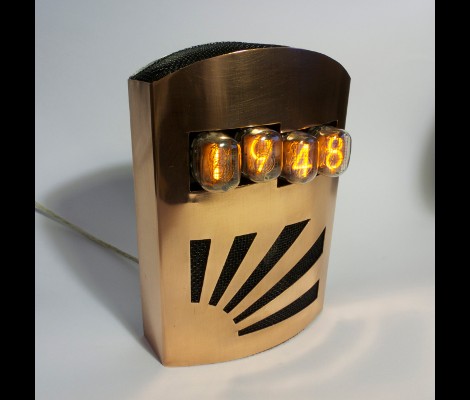
[Matt Evans] achieves a total win with his Nixie clock. Not only does he have the benefit of the retro display hardware, but he really catches our eye with the enclosure he built for it.

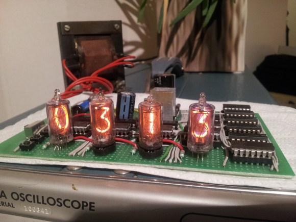
The project had its genesis when he came across a set of the Nixie Tubes in a surplus store. This was back in 2007, and with parts in hand he built the high-voltage driver circuit and a control board. The thing kept time, but was housed in a temporary case that was a bit rough looking. There it sat, waiting to become the focus of his attention once again.

When it did finally come time to build a proper case [Matt] started with a small sheet of recycled copper. He made the cutouts and bends by hand. He mentions that it’s a little uneven; maybe, but we don’t think it detracts from the design. Some black screen (like would be used on a porch door) covers the openings, giving texture and contrast to the facade.

We love the look, and the ATmega48 with a clock crystal for the RTC functions should make this a reliable time source.

Nixie Frequency Counter Gone Timepiece

nixie clock hack

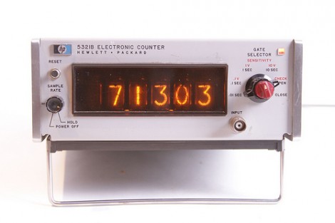
[Windell] of Evil Mad Scientist Laboratories took an ancient Nixie tube based frequency counter and converted it into a clock. The unit he got his hands on is an HP model that was still in great shape. He’s using an internally generated one second pulse as the clock signal, but some modifications are necessary to display time. That’s because the frequency counter is base 10 and clocks use a quirky combination of base 60 and base 12.

It wasn’t too much of a problem to rig up a system to track minutes and seconds. The tens digit for each is monitored by a couple of AND gates that he added to the mix. When they detect a ‘6’ the digit is reset and a pulse increments the next digit as the carry. This is more difficult to accomplish with the hours though. Minutes and seconds count from 0 to 59 but hours don’t start at 0. Instead of over-complicating the logic [Windell] used a bit of slight-of-hand. The Nixie tubes for the hours have been rewired so that when the counter is at 0, the filament in the shape of a 1 lights up. No difference in logic, just a translation that makes them display one digit higher than the actual count.

Steampunk Nixie Clock

This single-digit Nixie clock is a thing of beauty. You might hate Steampunk or you might love it, but you have to respect projects where the design gets equal (or more) consideration compared to the function. The electronics used in the project build upon an existing single Nixie design. Instead of hiding the guts inside the clock the PCB has been laid out to augment the design. We think [Blue Metal] hit it out of the park with this one!

ArduiNIX: Nixie Shield For Arduino

ArduiNIX-nixie-shield

Flock of Butterflies has just published their third post in a series about the ArduiNIX, an Arduino shield that drives Nixie tubes.We’ve featured Nixie tube projects such as a single tube clock, free-formed Nixie circuits, and tubes in a bottle. Now the hurdle of handling high voltage tubes while protecting low voltage logic circuitry has been taken care of for you. The shield can be purchased as a kit but the Eagle CAD files are also available, allowing you to etch your own circuit board.

Although this is meant for the Arduino there is nothing to keep you from using it as a driver with any microcontroller. The board listens for 5V logic levels to switch the multiplexed display of up to eight tubes. Get your hands on some Nixies and give this a try yourself.

Related: ArduiNIX Part 1, ArduiNIX Part 2

Working With VFDs

vfd

We love old display technology, like Nixie tubes, but they’re often difficult to work with because they require higher voltages than digital logic. Vacuum florescent displays (VFD) fall into this category. While not necessarily “old”, they are becoming far less common than LCDs. The main benefit of a VFD is that it actually produces light directly; it doesn’t require a backlight. You’ll find these displays on various players and appliances: CD, DVD, VCR, microwaves, stoves, car headunits, and others.

[Sprite_tm] had written off some VFDs, but recently revisited them with renewed interest. He started by testing what sort of voltage would be required to drive the display. It took 3V for the filament plus 15V to drive the grids. There are VFD controller chips available, but he wanted to get this working with what he had on hand. He had experience with older 40xx series logic, which can be powered by much higher voltages than 5V 74xx. His final schematic has three 4094 serial to parallel chips with an ATtiny2313 controller. A 5V power supply is dropped to 3V with diodes to drive the filament while a boost converter brings it up to 15V for the 4094s that switch the segments. While the code is specific to this display, it would be a great place to start your own project.