WiFi Hides Inside A USB Cable

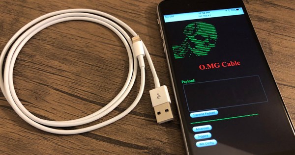
If you weren’t scared of USB cables before, you should be now. The O.MG cable (or Offensive MG kit) from [MG] hides a backdoor inside the shell of a USB connector. Plug this cable into your computer and you’ll be the victim of remote attacks over WiFi.

You might be asking what’s inside this tiny USB cable to make it susceptible to such attacks. That’s the trick: inside the shell of the USB ‘A’ connector is a PCB loaded up with a WiFi microcontroller — the documentation doesn’t say which one — that will send payloads over the USB device. Think of it as a BadUSB device, like the USB Rubber Ducky from Hak5, but one that you can remote control. It is the ultimate way into a system, and all anyone has to do is plug a random USB cable into their computer.

In the years BadUSB — an exploit hidden in a device’s USB controller itself — was released upon the world, [MG] has been tirelessly working on making his own malicious USB device, and now it’s finally ready. The O.MG cable hides a backdoor inside the shell of a standard, off-the-shelf USB cable.

The construction of this device is quite impressive, in that it fits entirely inside a USB plug. But this isn’t a just a PCB from a random Chinese board house: [MG] spend 300 hours and $4000 in the last month putting this project together with a Bantam mill and created his own PCBs, with silk screen. That’s impressive no matter how you cut it.

Future updates to this cable that will hack any computer might include a port of ESPloitV2, an Open Source WiFi controlled USB HID keyboard emulator. That will bring a lot of power to this device that’s already extremely capable. In the video attached to this tweet you can see the O.MG cable connected to a MacBook, with [MG] opening up a webpage remotely.

Amazing SDR Built By 16 Year Old

[Lukas] started his epic SDR-from-scratch build when he was 16. Projects like this aren’t completed overnight. (He’s now 18. We’re impressed.)

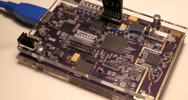
The project itself is a Software-Defined Radio built on top of the 12-bit Analog Devices AD9364 transceiver IC. A big fat FPGA takes the data and runs it off to a USB 3.0 interface, which is necessary for the amount of data this thing will be producing — he’s got it receiving 56 MHz of bandwidth. In short, this is an SDR peripheral that’s in the big leagues.

After two years of work and (only!) three revision, [Lukas] got the thing working. Read his writeup for the blow-by-blow account. In the end, a 6-layer board was necessary for the routing to get the full speed out of the clocking, and he discovered the reason that you use exactly the specified bias resistors — the expensive ADC chip gets very hot. But he didn’t give up, and in the end he pulled off a project of immense complexity. In his own words:

I have discovered that taking on large projects, even when not knowing how to tackle problems that might arise, is a very effective way of learning for me. It’s just important to be persistent, as I’ve seen that almost any problem can be solved on your own — which is incredibly rewarding — even if you get stuck and seem to not make progress for a while.

[Lukas] is now working on the software. He’s already got a hacked osmocom driver working, so it plays nice with GNURadio.

Of course, there are tons of ways to get into SDR without building your own from scratch, but we applaud [Lukas] for going the hard way. If you’re tempted to follow in his footsteps, have a look at [Michael Ossmann]’s great talk on making the RF design process as tractable as possible.

Ceci N’est Pas Une Clock

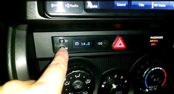
[Justin] tipped us about his slick custom OBD-II gauge that could easily pass for an OEM module. He was able to use the clock area of his Subaru BRZ to display a bunch of information including the oil and coolant temperatures and the battery voltage.

The forum post linked above has a good FAQ-based explanation of what he did, but so many people have told him to shut up and take their money that he created an Instructable for it. Basically, he’s got a Sparkfun OBD-II UART board communicating with a pro Trinket. The display is an Adafruit OLED, which he found to be an ideal choice for all the various and sundry light conditions inside the average car.

[Justin] was able to reuse the (H)our and (M)inute buttons and reassigned them to (H)igh to show the peak reading and (M)ode to, well, switch between modes. The (:00) now resets the peak readings. He offers suggestions for acquiring the specific CAN codes for your car to make the data more meaningful. [Justin]’s code is safe in the many tentacles of Octocat, and you can check out his demo video below.

Continue reading “Ceci N’est Pas Une Clock”