Battery Backup For RasPi Keeps Your Data Safe

We’ve all raised a clench fist in anger over lost data, and it’s usually the result of unjustified optimism and lack of planning. [George] shared his solution that prepares for the worst: a circuit that provides backup power to a RasPi and its hard drives. [George’s] Pi setup runs as both an Apple Time Machine server and a website backup server, and a power outage could corrupt the data stored on the Pi’s attached hard drives.

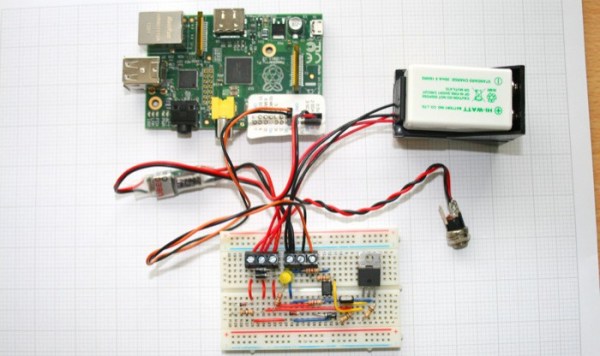
Rather than turn to commercial solutions, however, [George] wanted to take advantage of the Pi’s low power consumption and create an inexpensive custom circuit that would safely and automatically power down the devices upon loss of power. To detect a power failure, the build connects one of the Pi’s GPIOs to an opto-isolator, which—through a zener diode—connects to the 12V wall adapter: though [George] welcomes suggestions for alternative methods of safely identifying a mains power loss. The rest of the circuit serves as a trickle charger for the two attached 9V batteries and as a regulator to supply the correct voltage to the RasPi. Power MOSFETs connected to a GPIO handle the delayed power off.

You can view (and edit!) the circuit online here and find the relevant source code on [George’s] website. If you want to build your own RasPi file server, try cramming all the parts into an old optical drive enclosure.

Build Your Own Programmable Logic Controller

[Q] is an Electrical Engineer who works in an industrial setting. He frequently uses Programmable Logic Controllers at work but had never built one himself. He decided to undertake the project at home and managed to build a PLC that outputs 120V AC or 12 V DC and has optoisolated inputs.

On the circuit board you’ll find an ATmega8 and an EEPROM for extra data storage. Six outputs are controlled by relays since they are able to output either alternating or direct current. There are eight inputs which use optical isolators as buffers to protect the microcontroller.

So what did he end up using this for? It was part of his Christmas light setup last year. The image above shows the PLC in a water-tight electrical box with extension cords running to each of the devices he wishes to control. The example code is what he used on the X-mas setup, but it should be enough of a guide to program this to work with just about any application.

WAP Controlled Home Automation

homeauto

[Josh] sent in a home automation project he did a little while ago. It has a total of eight switched outlets. The main focus of the project was WAP access for remote control from any cellphone. The control box is based on a design by [Ashley Roll] for controlling eight servos using a PIC microcontroller. A listener app written in Java monitors the control web page and sends signals to the board via serial port. He used opto-isolated 240V solid state relays for each of the outlets. All the pieces are available on the site and he might even do a custom control board design if there is enough interest.