10 Meter Long Moving Light Show Is Mesmerizing

light-show

[Marcus] was recently commissioned to put together the electronics for a slick 10 meter long LED installation at the Hsinchu Biomedical Science Park Exhibition Center in Taiwan. While you might assume that he was asked to construct a large LED matrix, this project is a little bit different from what you probably expected.

The display is actually a long light tunnel made up of 30 moving triangles suspended from the ceiling. The triangle movement is governed by 60 separate stepper motors, while the lighting is provided by 30 HL1606 RGB LED strips he picked up from Adafruit. The display’s logic is handled completely by an XMOS controller, which is beefy enough to handle controlling all of the stepper motors and the LEDs simultaneously.

After he hand assembled all of the motor driver boards and tested things in his workshop, the whole lot was shipped over to Taiwan for assembly by the on-site crew. After a bit of troubleshooting, they were able to get things working properly, and the display looks great as you can see from the image above.

[Marcus] says that he doesn’t have video of the display in action just yet, though he will update his post whenever he does.

[Thanks, Paul]

Insanely Kludgy Pen Plotter Actually Works

This pen plotter, held together with structural epoxy, is an amazing piece of engineering, and almost as impressive as a bridge made entirely out of Bondo.

[Brian] at the Rochester, NY hackerspace Interlock needed to build something for the BarCamp geek “unconference.” To lure BarCamp attendees over to the Interlock table, they needed a small tabletop device with whirring motors that was able to make some decent swag. Hacking together a pen plotter sounded like the perfect project.

The mechanics of the build were scavenged from old printers and scanners. [Brian] decided to use pin-feed card stock, so the take-up wheels from an old dot matrix printer was sacrificed as well. This paper feed mechanism serves as the Y axis, and the X axis rides above the paper on precision rods. The pen holder is supported by a tiny solenoid.

Things start getting crazy at the software level. grbl was loaded onto an Arduino with a stepper driver shield, and vector text drawings were printed. After a bit of live-action hackery, [Brian] figured out how to plot captured webcam images. OpenCV captures and does a trace outline. This is converted to vectors with autotrace, and from EPS to HPGL by pstoedit. A Python script then cleans up the HPGL and converts it to G code and sends it to the printer. Confused? So are we, so just check out the video of the plotter in action after the break.

Continue reading “Insanely Kludgy Pen Plotter Actually Works”

Pololu Compatible Relay Driver

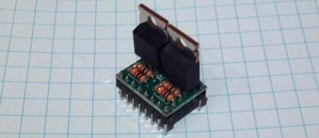
[Bart] built a couple dozen Pololu compatible relay drivers.

If you have a Reprap, you’re probably familiar with the Pololu stepper motor driver. These tiny pieces of kit provide stepper motor control for Gen 6, RAMPS, or Sanguinololu Reprap electronics. There’s a small problem with all these boards, though; there’s no way to control any high-power devices from these boards except for stepper motors. Controlling a spindle for a home-built CNC router would be great, but apart from attaching a Dremel to your x-axis, you’re just about out of luck.

[Bart]’s relay driver takes the step and direction inputs from the stock Pololu stepper driver and connects each of those to a MOSFET. From there, a relay can be hooked up to the driver to control the spindle for a router, or a whole bunch of fans for a homebrew laser cutter.

The schematic and Gerber files are up on [Bart]’s webzone. The part count is very low, and the entire board could easily be built on a piece of perfboard. Check out the demo on the other side of the jump.

Continue reading “Pololu Compatible Relay Driver”

The Concepts Behind Robotic Maze Solving

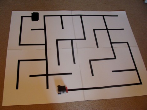
[Patrick McCabe’s] latest offering is a well-built maze-solving bot. This take on the competitive past-time is a little more approachable for your common mortal than the micro-bot speed maze solving we’ve seen. Don’t miss seeing the methodical process play out in the clips below the fold.

The playing field that [Patrick’s] robot is navigating is made up of a electrical-tape track on a white background. The two-inch tall double-decker bot is every economical. It uses an RBBB Arduino board to read an optical reflectance sensor array made by Pololu, then it drives a couple of geared motors using an L293D h-bridge breakout board. But we already know that [Patrick’s] a talented robot builder, this time around we’re happy to see his in-depth discussion of how to program a robot to solve a maze. In it he covers all of the different situations your robot might face and how to deal with them. Once you’ve dug through all of the concepts, dust off that bot you’ve got lying in the corner and start writing some new firmware.

Continue reading “The Concepts Behind Robotic Maze Solving”

Blu-ray Laser Plotter Writes On Glow-in-the-dark Screen

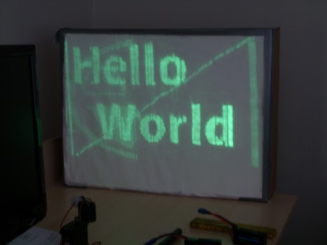
This laser display is persistent thanks to a glow-in-the-dark screen. [Daniel] built it using a Blu-ray laser diode. As the laser dot traverses the screen, it charges the phosphors in the glow material, which stay charged long enough to show a full image.

The laser head is simple enough, two servo motors allow for X and Y axis control. A Micro Maestro 6-channel USB servo controller from Pololu drives the motors, and switches the diode on and off. This board offers .NET control, which [Daniel] uses to feed the graphics data to the unit. Check out the video demonstration below the fold to see a few different images being plotted. It’s shot using a night-vision camera so that you can really see where the laser dot is on the display. It takes time to charge the glow material so speeding up the plotting process could actually reduce the persistent image quality.

This is yet another project that makes you use those geometry and trigonometry skills.

Continue reading “Blu-ray Laser Plotter Writes On Glow-in-the-dark Screen”

Retake On A Wii Remote Controlled Balancing Robot

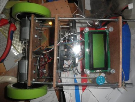
[Tijmen Verhulsdonck] built his own version of a Wii remote-controlled balancing robot. He drew his inspiration from the SegWii, which was built by [Ara Kourchians].

The body is built using one of our preferred fabrication methods; threaded rod makes up a rail system, with three sheets of hard board serving as a mounting structure for the motors, electronics, and battery. This does away with the 9V batteries used on the original SegWii, opting for a very powerful lithium battery perched on the highest part of the assembly. It uses an Arduino as the main microcontroller. That detects roll, pitch, and tilt of the body by reading data from a Sparkfun IMU 5 board (we’re pretty sure it’s this one). Check out the videos after the break. The first demonstrates the robot balancing on its own, then a Wii remote is connected via Bluetooth and [Tijmen] drives it around the room by tilting the controller. The second video covers the components that went into the build.

This is impressive work for a 17-year-old. [Tijmen] lists his material cost at $800 but since he’s Dutch this might not be a USD currency.

Continue reading “Retake On A Wii Remote Controlled Balancing Robot”

A Collection Of Quick Line-followers

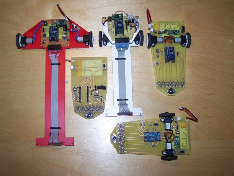
Here’s a nice collection of line-following robots (translated). They’re fast and they stay on track even through sharp turns. They center around a Baby Orangutan board which features an ATmega328 microcontroller and two motor driver channels. These drive the geared motors and use optical sensors to track a dark line on a light surface. There’s plenty of build and testing information (translated) if you’re interested in the gory details. Or just jump past the break to see the red on doing its thing.

Continue reading “A Collection Of Quick Line-followers”