The Quest For High Powered Blinky And Buzzing

Sometimes, we need devices to notify us of something. The oven timer is going off. Your phone has a push notification. The smoke detector battery is getting low. All of these problems can be solved with a buzzer or an LED. It’s a simple and cheap problem to solve.

But what if you need to know if something’s wrong with a diesel engine that throwing out 90 dB of noise? What if you’re not guaranteed to be around that engine? What if you need to tell everyone within a half mile that something is wrong. Again, LEDs and beepers, but the standard, off-the-shelf implementation isn’t going to cut it. You need massive amounts of buzzers and LEDs, and you’re going to need to drive them all with some reasonably high current. How do you solve that problem?

This is the problem [Tegwyn] had to solve for another one of his Hackaday Prize entries. The solution is what you would expect — buzzers and LEDs — but he’s putting some serious current behind these devices. There are, in fact, thermal considerations taken into account when you’re beeping this many buzzers.

The LEDs for this project are a handful of blindingly bright 1209 and 1206 SMD parts, and the buzzer is an obnoxiously loud SMD 97 dB buzzer. There are eight buzzers on this board. So, how do you drive these power-hungry devices? [Tegwyn] is using an L293E half-bridge motor driver, in a ‘Power-DIP’ package for relatively effective heat dissipation. Does it work? Oh, yes, and it’s very annoying. Take a look at the video below and judge for yourself. You can, indeed, make something louder and more annoying by adding more power.

Continue reading “The Quest For High Powered Blinky And Buzzing”

Junk Bin Self Balancing Bot With ESP8266

As we all know, sometimes the projects we plan simply never materialize. You have an idea, maybe even buy some of the parts you need, and then…nothing. Maybe you changed your mind, or maybe the idea was never that good to begin with. In any event, time marches on, the parts pile up, and the ideas come and go. Such is the life of the hacker.

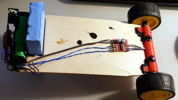
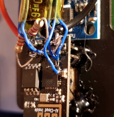
[Andrius Mikonis] writes in to tell us how his graveyard of abandoned projects ended up providing exactly what he needed to embark on a project he’s been fascinated with for years: the two-wheel self balancing robot. He started with a motor and wheel set that was originally intended to be part of a rover, added an accelerometer, and tied the whole thing together with an ESP-01 he had lying around. The final result certainly looks the part, and goes to show that projects don’t always need to be 1000 hour labors of love to accomplish their goals.

The construction of this little bot is simple in the extreme. A piece of plywood makes up the primary structure, with the wheels glued to the bottom and the electronics taking up residence in the top. It’s powered by two lithium battery cells that were salvaged out of an old laptop, with a DC-DC buck converter to provide a stable 3.3 VDC for the ESP-01 and MPU6050 accelerometer. To control the motors themselves, [Andrius] is using a cheap L293 controller that he found on eBay.

For interactive control, [Andrius] is making use of the ESP’s Wi-Fi to provide a web-based interface. This lets you control the bot from essentially any device that has a browser, rather than having to use a dedicated hardware transmitter.

Self-balancing robots of various levels of complexity are a relatively common project in the hacker world. There’s just something magical about the way they scoot around, seeming to defy gravity.

A Stepper Motor For Two Dimensions

We’ve all heard linear motors, like those propelling Maglev trains, described as “unrolled” versions of regular electric motors. The analogy is apt and helps to understand how a linear motor works, but it begs the question: what if we could unroll the stator in two dimensions instead of just one?

That’s the idea behind [BetaChecker’s] two-axis stepper motor, which looks like it has a lot of potential for some interesting applications. Build details are sparse, but from what we can gather from the videos and the Hackaday.io post, [BetaChecker] has created a platen of 288 hand-wound copper coils, each of which can be selectively controlled through a large number of L293 H-bridge chips and an Arduino Mega. A variety of sleds, each with neodymium magnets in the base, can be applied to the platen, and depending on how the coils are energized, the sled can move in either dimension. For vertical applications, it looks like some coils are used to hold the sled to the platen while others are used to propel it. There are RGB LEDs inside the bore of each coil, although their function beyond zazzle is unclear.

We’d love more details to gauge where this is going, but with better resolution, something like this could make a great 3D-printer bed. If one-dimensional movement is enough for you, though, check out this linear stepper motor that works on a similar principle.

Continue reading “A Stepper Motor For Two Dimensions”

Bluetooth Stepper Motor Driver

bluetooth-stepper-motor-driver

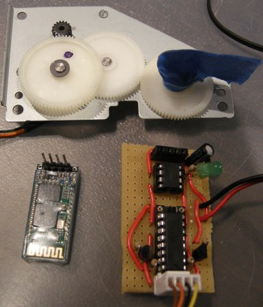
[Dan] salvaged some parts from an old printer a while back and finally found some time to play with them. One of the things he was most interested in is the geared stepper motor seen above. He was able to get it running with an Arduino in no time so he decided to take the project a little bit further. What he ended up with is a stepper motor driver which can be controlled over Bluetooth.

The motor can’t be driven directly, but with a simple motor driver like the L293 chip [Dan] used it’s not hard to interface them with your control hardware of choice. From there he added an ATtiny85 which will take care of the stepping protocol necessary to move the motor. The Bluetooth module he’s using functions as a serial device, making it really simple to interface with the uC. [Dan] uses a pin header to connect the module, so switching to a different type of serial device in the future will be quick and painless.

After the break you can see him sending step commands to the driver board.

Continue reading “Bluetooth Stepper Motor Driver”

GSM Controlled Car Without Needing A Microcontroller

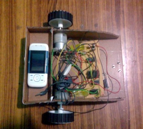
Nope, no microcontroller here, just a full-blown cellphone used as the brains of this little robot. The secret behind how it works is in the sounds the phone makes. The touch tones, known as DTMF, are monitored by the circuit mounted on the front half of the chassis and are responsible for driving the motors.

[Achu Wilson] built the circuit around an MT8870 chip which decodes the DTMF sounds and uses the BCD output to feed some logic chips. A 4 line to 16 line decoder and an inverter chip format the signals for use as inputs to the L293D motor driver. The video after the break shows him driving the rover directly by pressing number on the phone (like a tethered remote control). But he mentions that it’s possible to call the phone and press the numbers remotely. We assume you need to connect the call manually as we see no way to automatically answer calls.

This is certainly a fun way to play around with the DTMF protocol.

Continue reading “GSM Controlled Car Without Needing A Microcontroller”

The Concepts Behind Robotic Maze Solving

[Patrick McCabe’s] latest offering is a well-built maze-solving bot. This take on the competitive past-time is a little more approachable for your common mortal than the micro-bot speed maze solving we’ve seen. Don’t miss seeing the methodical process play out in the clips below the fold.

The playing field that [Patrick’s] robot is navigating is made up of a electrical-tape track on a white background. The two-inch tall double-decker bot is every economical. It uses an RBBB Arduino board to read an optical reflectance sensor array made by Pololu, then it drives a couple of geared motors using an L293D h-bridge breakout board. But we already know that [Patrick’s] a talented robot builder, this time around we’re happy to see his in-depth discussion of how to program a robot to solve a maze. In it he covers all of the different situations your robot might face and how to deal with them. Once you’ve dug through all of the concepts, dust off that bot you’ve got lying in the corner and start writing some new firmware.

Continue reading “The Concepts Behind Robotic Maze Solving”

Roll Away Clock Becomes A Programmable Rover

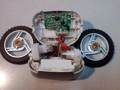
The parts laid bare in the picture above all make up a roll away alarm clock that flees when you don’t get out of bed. It’s an interesting idea, but considering most folks don’t sleep on hardwood floors we can understand why [TheRafMan] was able to pick this gem up for under $5. That’s quite a deal because there’s a very usable LCD module at the top. But for this hack, he focused on using the gearhead motors to make a programmable rover.

In order to make this programmable [TheRafMan] had to add a microcontroller. He chose an Arduino variant, called the Ardweeny. It’s a board that piggy-backs the ATmega328. But he didn’t use a stock Ardweeny; he’s altered it to play nicely with jumper wire. The uC is able to interface with the gearhead motors thanks to an L293D h-bridge motor driver chip. As you can see in the clip after the jump, the rover can now be driven around using a Wii Nunchuck or via a USB connection. If you’ve got a Bluetooth module lying around it wouldn’t be hard to make this a wireless solution that can be controlled with the accelerometers in a Wii remote.

Continue reading “Roll Away Clock Becomes A Programmable Rover”