Repairing A Junked Signal Generator

We must be walking past the wrong dumpsters because we certainly haven’t encountered equipment like this just waiting to be salvaged. [Shahriar] found an HP 8648C Synthesized Signal Generator while he was ‘dumpster diving’ and set out to fix the malfunctioning lab equipment. He posted a 1-hour video on the project, which you can find embedded after the break. The actual fix happens in the first half, the rest of the video is spent testing the resurrected device.

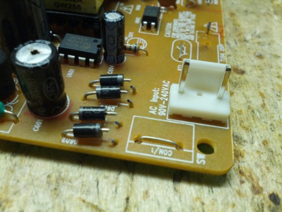
The back corner of the case has been dented, which may be the reason this has been thrown out. When it is first powered it emits an unpleasant screeching noise and the user interface doesn’t do anything. [Shahriar] says he recognizes the sound as a malfunctioning switch-mode power supply. Sure enough, when disconnected from the main board it still makes the noise. It turns out there’s a huge electrolytic capacitor the size of a stack of poker chips which has come loose from the PSU board. When it’s resoldered the device fires up as expected.

Now how are we going to find a digital capture oscilloscope that just needs to have its PSU reassembled?

Continue reading “Repairing A Junked Signal Generator”

Problems Powering Raspberry Pi From GPIO Header

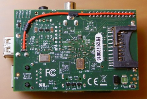
[Zaion] grabbed an ATX power supply to source the 5V the Raspberry Pi needs to run. The common problem when it comes to RPi supplies is a shortfall in how much current a USB wall adapter can source. The ATX shouldn’t have this problem, but none-the-less he found that the USB ports were only reading about 5V. Strange. He grabbed the soldering iron and fixed the issue with a piece of jumper wire (English translation found in the second half of his post).

The problem was discovered when trying to get a WiFi dongle to work on one of the RPi’s USB ports. It simply wouldn’t show up, and after going down the blind alley of assuming it was a driver problem he started to investigate the hardware. After discovering the below-nominal voltage [Zaion] measured the resistance between the 5V pin on the GPIO header and the one on the USB port. It reads 3-4 Ohms and he concluded that the trace is too thin. We took a quick look at the schematic for the board and see no reason for the voltage drop. His jumper wire fixed the issue but it leaves us wondering, is this an isolated case, or a design flaw? Tell us what you think in the comments section.

Switch Mode Breadboard Supply From A PTH08080

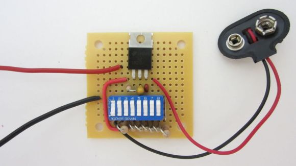
[Ben] wanted a switch mode power supply for his breadboard. He ordered a PTH08080 module which is made by Texas Instruments. The spec sheet would make it a great choice for him, but he was not happy to learn that the pinout doesn’t conform to the 0.1″ spacing used by solderless breadboards. His solution was to make a breakout adapter from some protoboard.

The PTH08080 can source up to 2.25A. It accepts 4.5-18V input and can output 0.9-5.5V. The best part is the efficiency that a switch mode supply achieves compared to linear regulators. This design adds in two capacitors which are suggested in the application circuit from the datasheet (PDF). Notice that there are two headers on the breakout board. One supplies power and ground to the breadboard. The other gives him a place to connect the adjustment resistor used to select the output voltage. This connects between one pin on the PTH08080 and GND. [Ben] plans to upgrade the design by included a precision trimpot for easy output voltage adjustments.

Buying Cheaper Electronics And Not Saving Money

As an engineer at Spectrum Design in Minneapolis, [Carl] works with clients to get their product out to the masses. When designing a new USB-powered device, one client thought it would be a great idea to include a USB car charger with the device. The client promptly ordered a few thousand car chargers from China and everything was going swimmingly.

Everything was fine, of course, until [Carl] decided to test the Chinese car chargers with the client’s device. The USB PHY burnt out in short order, and the likely culprit was a shorted 12 volt regulator. This demanded a closer inspection, so after cracking open the charger [Carl] was amazed at what he found.

Yes, what you see on that circuit board is accurate. The manufacturer of these car chargers never even populated the switched mode regulator for this car USB charger.  Amazing, considering a single 10 cent 7805 DC regulator would have almost worked for this application.

If there was ever an example of being careful when purchasing the cheapest possible product to increase profit margins, this would be it.

Ever the engineer, [Carl] sent this into the tip line as a Word document. That’s available here, along with a slide show of the pictures [Carl] snapped.

Continue reading “Buying Cheaper Electronics And Not Saving Money”

ATX Benchtop Conversion Retains Safety Features, Delivers Plenty Of Current.

atx-benchtop-psu

[Bogin] was looking to add a benchtop power supply to his array of tools, but he didn’t really find any of the online tutorials helpful. Most of what he discovered were simple re-wiring jobs utilizing LM317 regulators and shorted PS-ON pins used to keep the PSUs happily chugging along as if nothing had been changed. No, what [Bogin] wanted was a serious power supply with short circuit protection and loads of current.

He started the conversion by disassembling a 300 watt ATX power supply that uses a halfbridge design. After identifying the controller chip, a TL494 in this case, he proceeded to tweak the PWM feedback circuit which controls the supply’s output. A few snips here, a few passes with a soldering iron there, and [Bogin] was ready to test out his creation.

He says that it works very well, even under heavy load. His tutorial is specific to these sorts of PSUs, so we would be more than happy to feature similar work done with those that implement other design topologies. In the meantime, be sure to check out a video of the hacked power supply in action below.

Continue reading “ATX Benchtop Conversion Retains Safety Features, Delivers Plenty Of Current.”

Building A Bench Supply Without Altering The ATX Psu

[FozzTexx] has been using a bench supply he made from an AT PSU for years. He put a lot of work into that one, removing unnecessary wires, mounting banana plug jacks on the metal case, and adding an on/off switch and labels. But if it ever dies on him it will be a major pain to do all that work again in order to replace it. When he set out to build another bench supply from an ATX PSU he decided to do so without altering the PSU. This way he can easily swap it out for a different one if he ever needs to.

The hardest part of the hack was sourcing connectors. But with the parts in hand he’s able to just plug the faceplate into the stock connector. This gives him access to all of the voltages, and provides an on/off switch and indicator light. He might also want to add the option of resetting the unit if the over-current protection kicks in.

Bench Power Supply Resetting Thingy

As is common among some hackers, [Henry] re-purposed an ATX power supply unit to function as a bench power supply for testing circuits on a breadboard (much like this fancy example).

However, safety mechanisms on some modern PC PSUs do not automatically reset after over-current protection has kicked in, which soon became annoying for [Henry]. In order to make his power supply more hacker-friendly, he wired up and programmed an ATtiny85V, using some Arduino libraries, to do that for him. This simple project is a great example of using a hack to improve a pre-existing hack.