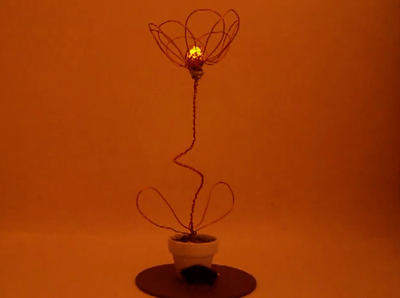
Electric Bike (earplugs Not Included)

It’s obvious this bike has some extra parts. But look closely and you’ll see the chainring has no chain connecting to it. Pedaling will get you nowhere since [PJ Allen] rerouted the chain in order to drive this bicycle using an electric motor.

He’s got beefy motor which pulls 350 Watts at 24 Volts. For speed control he opted to use an Arduino, pumping out PWM signals to some MOSFETs. This results in an incredibly noisy setup, as you can hear in the bench test video after the break. But once this is installed on the bike it doesn’t quiet down at all. You can hear the thing a block away.

The original road test fried the first set of 7A MOSFETs when trying to start the motor from a standstill. It sounds like the 40A replacements he chose did the trick through. We didn’t see any information on the battery life, but if he runs out of juice on the other side of town we bet he’ll be wishing he had left the chain connected to the crankset.

Continue reading “Electric Bike (earplugs Not Included)”

Adding The Apple ‘breathing LED’ To A Motorcycle

[spiralbrain] has a beautiful KTM Duke 200 motorcycle, but he’s found the factory configuration is a little bit plain. Wanting to add his own unique touch to his bike, he decided to add a ‘breathing LED’ to the parking light that slowly changes its brightness much like the LED on recent Macs.

From the factory, [spiralbrain]’s bike uses extremely inefficient (and somewhat ugly) T10 lamps for the parking light. This was changed over to a 12 Volt white SMD light bulb, but what really makes this build special is the way [spiralbrain] is controlling this lamp.

[spiralbrain] added a very tiny circuit consisting of an 8-pin microcontroller (a PIC12F683) that slowly dims the new SMD light bulb using the built-in PWM module. When the bike is taken out of neutral, the microcontroller stops at the highest PWM setting so the ‘breathing’ LED function is only engaged when not moving.

It’s an interesting mod that’s sure to draw some attention when [spiralbrain] is showing off his bike. As a bonus, the mod is completely reversible, so the bike’s warranty is still good.

Stair Accent Lights Made From Cheap LED Strips

We really like [Geert’s] take on accent lighting for his stairs. He built his own LED channels which mount under the bullnose of each step. The LED strips that he used are actually quite inexpensive. They are RGB versions, but the pixels are not individually addressable. This means that instead of having drivers integrated into the strip (usually those use SPI for color data) this strip just has a power rail and three ground rails for the colors. Ten meters of the strip cost him under forty dollars.

He did want to be able to address each step separately, as well as mix and match colors, so he designed the driver board seen above to use a set of TLC5940 LED drivers. These are controlled by the Arduino which handles color changing and animations. It will eventually include sensors to affect the LEDs as you walk up the stairs. Each strip is mounted in a piece of angle bracket, and they’re connected back to the driver board using telephone extension wire.

Floppy Drive As An Audio Sampler

Here’s a floppy drive which is being used as an audio sampler. At first glance we thought this was another offering which drives the stepper motor at a specific frequency to generate that characteristic sound at a target pitch. But that’s not what’s happening at all. The floppy is actually being used as a storage device (go figure).

From what we can tell, it’s being used almost like an 8-track tape. A PWM signal is stored on one circular slice of the disk, then the head can be moved back to that same “track” to play back the wave form. The head doesn’t move during playback, but just keeps reading the same track of bits. To the right you can see an Arduino board. This allows for MIDI control of the track selection. [Alexis] shows off some keyboard control in the video after the break. There’s a buffer chip on the breadboard which allows the audio output to be quickly switched off as the floppy drive head is moved. This keeps garbage out of the sound until the new track can be read.

Continue reading “Floppy Drive As An Audio Sampler”

Repair A Misbehaving Motor Controller Board

It can be a real drag to fix a circuit board which has stopped working as intended, especially if you don’t have any reference material for the product. That’s the position that [Todd Harrison] found himself in when the controller for his mini-lathe gave up the ghost. He undertook and hefty repair process and eventually mapped out and repaired the driver board.

First off, we’re happy to report his success at the end of a year-long troubleshooting process; the entirety of which occupies six different posts. The link at the top is the conclusion, and you’ll find his final test video after the break. But as you can see from the image above, he was met with a lot of problems along the way. The first two segments show him reverse engineering the PCB, with a giant schematic coming out of the process. In part 3 he then started probing the board while it was live, with the smell of hot electronics causing him to disconnect the power every thirty seconds. One time he took too long and blew a resistor with the pictured results.

In the end it was a shorted PWM chip to blame. He tested a couple of different replacement options, dropped in the new part, and is now back in business. Continue reading “Repair A Misbehaving Motor Controller Board”

Building A LED Strip The Minimal Way

For his first big build with an MSP430, [Javon] decided to an RGB LED fader. Having worked with Arduinos in the past, he figured that his MSP430 would have a few PWM channels. After being proved wrong by the data sheet, [Javon] needed to figure out a way to switch a bunch of RGB LEDs with only one PWM channel on his microcontroller.

Because there was only one PWM pin on [Javon]’s micro, he needed a way to multiplex his output. He ended up using a 74HC4052 mux/demux chip to drive 20 LEDs. The LEDs were mounted onto hard board and the main part of the circuit built on a bit of perfboard. While there’s no total cost for his build, we’re guessing [Javon] didn’t spend much on his project; certainty much less than this explosion of LEDs.

[Javon] put all the build pictures up as a Google+ album and a few video demos up. Check those out after the break (009 Sound System warning, you might want to hit mute).

Continue reading “Building A LED Strip The Minimal Way”

Dimming AC Lights The Hard Way

It’s that time of year again where the thermometer drops, the sun sets earlier, and we try to warm our hearts with the solstice festival that is common in our own respective cultures. Of course we all need a few strings of lights, but wouldn’t it be great if we had PWM controlled dimmable lights?

When he started out on his PWM-controlled, AC-powered light box, [Waterbury] immediately realized that relays were not going to be an optimal solution. The best way out of the mess he dug himself into would be via zero crossing. After getting a transformer wired up to a transistor for the detection circuit, a short bit of code was written in the wee hours of the morning and a proof of concept was had.

With the control box complete, [Waterbury] hacked up a quick VB app and piped the output of a WinAmp visualizer into the lights via serial. The Inception demo was great, but finer-grain control was needed. After seeing a Hack a Day post on a nice equalizer chip, the seven band output on IC were converted to UART.

[Waterbury] took his seven-band AC-controlled light box to a Halloween party with his synth and the results looked awesome. You can check that out after the break, but we’re really waiting to see his Christmas decorations this year.

Continue reading “Dimming AC Lights The Hard Way”