It turns out that as the days get shorter, chickens lay fewer eggs. But you can trick them into keep up production using artificial light. [Jpitz31] decided to build his own timed coop light to bridge the gap until the days of plentiful sunlight return.
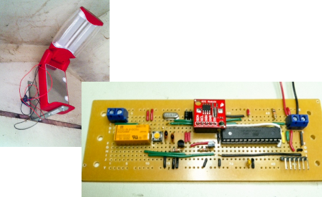
He already had an LED camping light to use, but needed to find a way to power it and to switch it on and off on a schedule. He chose an ATmega328 for the latter, as he had a bunch of extras sitting around. As for power, there isn’t AC available where the coop is, so he opted for a 12V lead-acid battery with hopes of adding solar charging features in the future.
Switching is handled by a relay, with accurate time kept by a DS1307 real-time clock (it’s the red PCB seen above). Everything fits nicely on the board, and we have a couple of feature suggestions for future improvements. The linear regulators will eat up some extra power so moving to a switching regulator will help save juice. Also, it would be very easy to add a light sensor so that the light will only be on when the ambient light drops to a preset level. This way he won’t need to mess with the schedule as the length of the days change.


