Arduino Versus Logic: The Coil Gun War Continues

Looks like another shot has been fired in the simmering Coil Gun Control War. This time, [Great Scott] is taken to the discrete woodshed with a simplified and improved control circuit using a single CMOS chip and a few transistors. Where will it end? Won’t somebody think of the children?

The latest salvo is in response to [GreatScott]’s attempt to control a DIY coil gun with discrete logic, which in turn was a response to comments that he took the easy way out and used an Arduino in the original build. [Great Scott]’s second build was intended to justify the original design choice, and seemed to do a good job of explaining how much easier and better the build was with a microcontroller. Case closed, right?

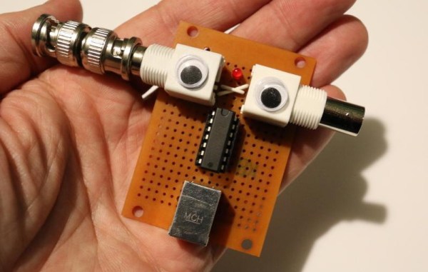
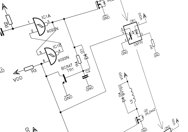
Nope. Embedded designer [fede.tft] wasn’t sure the design was even close to optimized, so he got to work — on his vacation, no less!’ He trimmed the component count down to a single CMOS chip (a quad Schmitt trigger NAND), a couple of switching transistors, the MOSFETs that drive the coils, and a few passives. The NANDs are set up as flip-flops that are triggered and reset by the projectile sensors, which are implemented as hardwired AND gates. The total component count is actually less than the support components on the original Arduino build, and [fede.tft] goes so far as to offer ideas for an alternative that does away with the switching transistors.

Even though [fede.tft] admits that [GreatScott] has him beat since he actually built both his circuits, hats off to him for showing us what can likely be accomplished with just a few components. We’d like to see someone implement this design, and see just how simple it can get.

Hackers Measure Cable Lengths With Time Domain Reflectometers

[android] has built up a fast edge pulse generator for time domain reflectometry (TDR). TDR is a neat technique which lets you measure cable lengths using electrical signals and can also be used to locate faults within the cable.

TDR works by sending a pulse down the cable. When the pulse reaches the end of the unterminated cable it is reflected back to the source. By monitoring the delay between the original pulse and its reflection you can determine the length of the cable. We’ve seen projects that use TDR before, and it’s often used in telecoms industry to locate faults in long cable runs.

You can try TDR in your lab using only a scope to observe the delay and a function generator to create the pulse. However, the technique works a lot better with pulses that have very fast rise times. So [android] built a fast edge pulse generator based on [w2aew]s design. Then added googly eyes for good measure. His build works great and is a nice demonstration of the technique.

Reverse Engineering Silicon

[John McMaster] is doing some pretty amazing work with figuring out how the circuitry in an integrated circuit works. Right now he’s reverse engineering a serial EEPROM chip one section at a time. This is a 24c02 made by ST, and  he chose this particular portion of the die to examine because it looked like there were some analog components involved.

He removed the top metal using hydrofluoric acid in order to take this image. By continually removing layers this way he manages to work out the traces and even the components themselves. To help clarify the parts he uses the set of snapshots to generate a colored map using Inkscape. From there he begins labeling what he thinks the components might be, and like a puzzle the pieces start falling into place one by one. From the Inkscape drawing he lays out a schematic, then rearranges the components to make the design easier to understand. Apparently this is a Schmidt trigger.

[Thanks George]

[Jeri’s] Dress Lights Up When Someone Invades Her Personal Space — Step Back Nerds!

[Jeri] threw down the geeky fashion gauntlet by building this LED enhanced dress. She chose to assemble the project for her trip to BarBot 2011, and we can’t think of a more appropriate setting for such a garment. It uses a motion sensor to set off a delayed pattern of blue lights hidden underneath the fabric.The best part of the hack is the instamatic camera. It looks like a fashion accessory, but it’s really hiding all of the circuitry for the lights.

Inside the camera a PIR sensor waits until it detects motion, sending a signal through an op-amp to the trigger circuitry. A 74LS14 Schmitt Trigger chip teams up with some resistor-capacitor timer circuits to build a delay chain for the LEDs. This way, after motion is detected the LEDs come on and off in a staggered pattern that doesn’t require a microcontroller and is very pleasing to the eye. See the Analog win for yourself after the break.

Continue reading “[Jeri’s] Dress Lights Up When Someone Invades Her Personal Space — Step Back Nerds!”

Light-sensing Circuit For Power Saving Applications

light_sensing_circuit

Instructables user [MacDynamo] was thinking about home security systems and wondered how much electricity is being wasted while such systems are powered on, but not activated. He pondered it awhile, then designed a circuit that could be used to turn a security system on or off depending on the time of day, but without using any sort of clock.

His system relies on a 555 timer configured as a Schmitt trigger, with a photoresistor wired to the reset pin. When the ambient light levels drop far enough, the resistance on the reset pin increases, and the 555 timer breaks out of its reset loop. This causes the circuit to power on whatever is connected to it. When the sun rises, the resistance on the reset pin drops and the 555 timer continually resets until it gets dark again. He notes that this behavior can be easily reversed if you were to put the photoresistor on the trigger pin rather than the reset pin.

We like the idea, though we are a bit wary about using this for any sort of real security system. An errant insect or debris could cause the system to be turned on, and we’d feel pretty foolish if someone disabled our alarm with a flashlight. That said, this sort of circuit still has plenty of practical, power-saving applications outside the realm of home security.

Simple MIDI Thru Box

midithru

[Aris] has quite a few MIDI devices that only have in and out ports. To chain together multiple devices, the MIDI slaves must have a “thru” port. Instead of daisy chaining, a better solution is to build a thru box to split the signal from the master. [Aris]’s thru box design uses an optocoupler on the input, which connected to 74HC14 hex inverting Schmitt trigger. The schematic shows three outputs, but there’s room for adding two more. A useful bit of kit for only a two hour job.