Almost everyone who is involved with 3D printing thinks to themselves at some point, “this could all be done using a closed-loop system and DC motors”. Or at least everyone we know. There’s even one commercial printer out there that uses servo control, but because of this it’s not compatible with the rest of the (stepper-motor driven) DIY ecosystem.
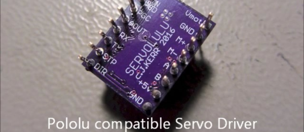
[LoboCNC] wanted to change this, and he’s in a unique position to do so, having previously built up a business selling PIC-based servo controllers. His “servololu” is essentially a microcontroller and DC motor driver, with an input for a quadrature encoder for feedback. The micro takes standard step/direction input like you would use to drive a stepper motor, and then servos the attached DC motor to the right position. It even signals when it has an error.
Continue reading “Is It A Stepper? Or Is It A Servo?”