Love them or hate them, Nixies are here to stay. Their enduring appeal is due in no small part to the fact that they’re hardly plug-and-play; generating the high-voltage needed to drive the retro displays is part of their charm. But most Nixie power supplies seem to want 9 volts or more on the input side, which can make integrating them into the typical USB-powered microcontroller project difficult.
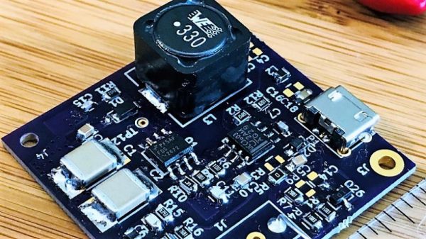
Fixing that problem is the idea behind [Mark Smith]’s 5-volt Nixie power supply. The overall goal is simple: 5 volts in, 170 volts out at 20 mA. But [Mark] paid special care to minimize the EMI output of the boost converter through careful design, and he managed to pack everything into a compact 14-cm² PCB. He subjected his initial design to a lot of careful experimentation to verify that he had met his design goals, and then embarked on a little tweaking mission in KiCad to trim the PCB’s footprint down by 27%. The three separate blog posts are well worth a read by anyone interested in learning about electronics design.
Now that [Mark] has his Nixie power supply, what will become of it? We can’t say for sure, but it’ll be a clock. It’s always a clock. Unless it’s a power meter or a speedometer.