Humans have always wanted to make small things bigger. To see that which is unseen with the naked eye. The inventor of the original microscope happened sometime in the 1600’s, though the inventor is still contested. Some say it was Cornelis Drebbel, while others say Hans Lippershey. Galileo Galilei’s compound microscope is probably the most well-known ancient magnifier. Regardless of who created the device, hackers, makers, engineers, and scientists have used microscopes to study mysteries of biology, geology, electronics, and just about anything else you can imagine.
This is a fitting topic for this week’s Hacklet at is aligns well with the Citizen Scientist challenge round of the Hackaday Prize which began on Monday. Making quality microscopes more widely available is one of many great starting ideas for an entry. Let’s take a look at some of the best microscopy projects on Hackaday.io!
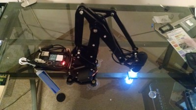 We start with [J. Kha] and Armed Microscope. [J. Kha] was one of the backers of the original uArm over at Kickstarter. He also does quite a bit of work with electronics. After fighting with a cheap USB microscope, he realized he had the perfect platform to control it. Microscopes usually are stationary, with the object being viewed moved on a stage. [J. Kha] turned things upside down by mounting the microscope on his uArm. An Arduino Yun controls the system. The Yun also allows him to stream the microscope’s video over the internet using the mjpg-streamer library. [J. Kha] did have some power issues at first, but he’s got his regulators all sorted out now.
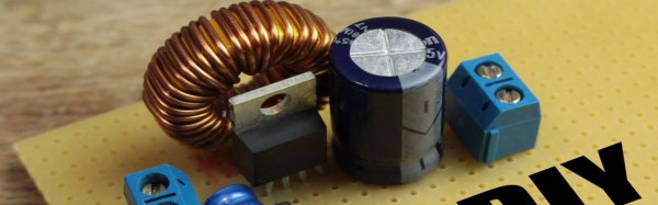
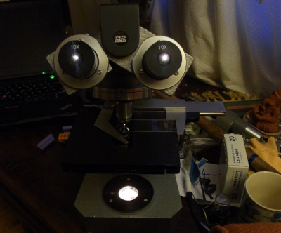 Next we have [andyhull] with Adding a light touch to a “classic” microscope. A lucky dumpster find netted [Andy] a pile of old broken microscopes. From this he was able to build a working classic stereo scope. This was a Gillet & Sibert stereo compound scope. Like most microscopes of its time, the old GS used standard incandescent or halogen lights for illumination. The old bulbs were long gone, and would have been a pain to replace. [Andy] switched his scope over to LED illumination. He ended up using a commercially available LED “bulb” designed to replace type 1157 automotive tail light bulbs. This type of LED is designed to run on 12 volt power which simplifies the wiring. The small LED flashlight in a custom mount also provides a bit of help for opaque subjects.
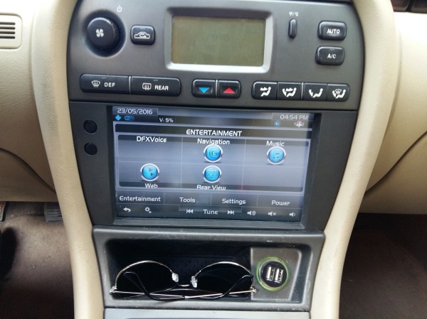
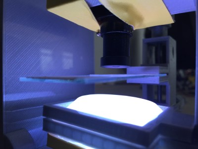 Next up is [Andre Maia Chagas] with Flypi – cheap microscope/experimental setup. Flypi is [Andre’s] entry in the 2106 Hackaday Prize. Flypi is more than just a microscope, it’s a 3D printed data collection and image analysis device for hackers and scientists alike. A Raspberry Pi 2 or 3 controls the show. Images come in through Pi Camera with an M12 lens. The Pi runs some open source Python code allowing it to acquire and analyze images. It also has an Arduino as a co-processor to handle anything a particular experiment may need – like RGB LEDs, heaters, manipulators, you name it. Andre sees Flypi as having uses in everything from fluorescence imaging to optogenetics and thermogenetics.
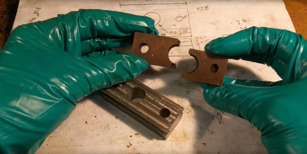
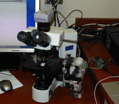 Finally we have [Jarred Heinrich] with Stagmo: Microscope Stage Automator. Positioning samples under high magnification requires a steady hand. Trying to image them makes things even harder. To help with this, microscopes have stages. Fine lead screws manually controlled by knobs allow the user to precisely position any subject. Automated stages are available as well, but they can get quite expensive. [Jarred] recognized that the microscope stage is an X-Y platform like any CNC, laser, or 3D printer. He used an Arduino and a motor shield to control a couple of stepper motors. The motors are coupled to the stage knobs with rubber belts. While the mounting system looks a little wobbly, but it got the job done, and didn’t require any modifications to the microscope itself.
Optical microscopes are just one type of scope you’ll find on Hackaday.io. There are also atomic force microscopes, scanning electron microscopes, and more! I’ll cover those on a future Hacklet. If you want to see more awesome optical microscopy projects, check out our new optical microscope projects list! If I missed your project, don’t be shy, just drop me a message on Hackaday.io. That’s it for this week’s Hacklet. As always, see you next week. Same hack time, same hack channel, bringing you the best of Hackaday.io!