Guitar effects have come a long way from the jangly, unaltered sounds of the 1950s when rock and roll started picking up steam. Starting in large part with [Jimi Hendrix] in the 60s, the number of available effects available to guitarists snowballed in the following decades step-by-step with the burgeoning electronics industry. Now, there are tons of effects, from simple analog devices that would have been familiar to [Hendrix] to complex, far-reaching, digital effects available to anyone with a computer. Another thing available to modern guitarists is the ability to model these effects and guitars in circuit simulators, as [Iain] does.
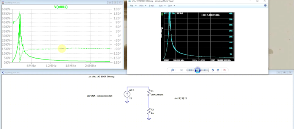
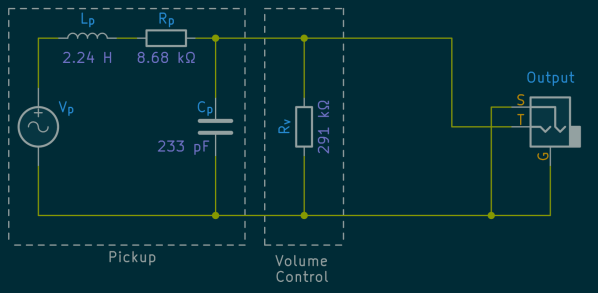
[Ian] plays a Fender Stratocaster, but in order to build effects pedals and amplifiers for it with the exact desired sound, he needed a way to model its equivalent circuit. For a simple DC circuit, this isn’t too difficult since it just requires measuring the resistance, capacitance, and inductance of the overall circuit and can be done with something as simple as a multimeter. But for something with the wide frequency range of a guitar, a little bit more effort needs to go into creating an accurate model. [Iain] is using an Analog Discovery as a vector network analyzer to get all of the raw data he needs for the model before moving on to some in-depth calculations.
[Iain] takes us through all of the methods of figuring out the equivalent impedance of his guitar and its cabling using simple methods capable of being done largely by hand and more advanced techniques like finding numerical solutions. By analyzing the impedance of the pickup, tone and volume controls, and cable, this deep dive into the complexities of building an accurate equivalent circuit model for his guitar could be replicated by anyone else looking to build effects for their specific guitars. If you’re looking for a more digital solution, though, we’ve seen some impressive effects built using other tools unavailable to guitarists in days of yore, such as MIDI and the Raspberry Pi.