Printed Jig Is A Welding Rig

[NixieGuy] was scheming to build robots with cable-driven joints when the pandemic hit. Now that component sourcing is scarce, he’s had to get creative when it comes to continuous cables. These cables need to be as seamless as possible to avoid getting caught on the pulleys, so [Nixie] came up with a way to weld together something he already has on hand — lengths of .45mm steel cable.

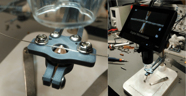
The 3D printed jig is designed to be used under a digital microscope, and even clamps to the pillar with screws. Another set of screws holds the two wires in place while they are butt welded between two pieces of copper.

[Nixie] adds a spot of solder paste for good measure, and then joins the wires by attaching his bench power supply set to 20V @ 3.5A to the copper electrodes. We love that [Nixie] took the time to streamline the jig design, because it looks great.

This just goes to show you that great things can happen with limited resources and a little bit of imagination. [Nixie] not only solved his own supply chain problem, he perfected a skill at the same time. If you don’t have a bench supply, you might be able to get away with a battery-powered spot welder, depending on your application.

Conductive Tape Current Capacity Comparison

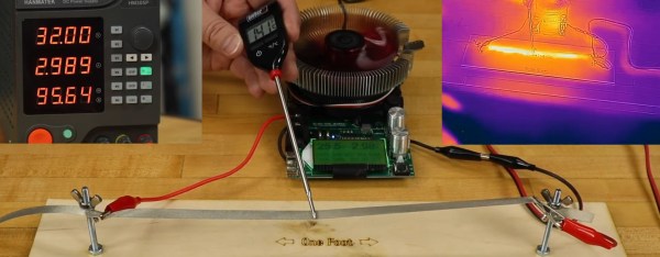
The world of DIY circuits for STEM and wearables has a few options for conductors. Wire with Dupont connectors is a standard, as is adhesive copper tape. There’s also conductive nylon/steel thread or ribbon. Which you choose depends on your application, of course, but as a general rule wire is cheap and ubiquitous while making connections is more challenging; copper tape is cheap and simple to use, but delicate and rips easily, so is best used for flat surfaces that won’t see a lot of stress or temporary applications; and conductive nylon thread or tape is better for weaving into fabrics.

The Brown Dog Gadgets team wanted to respond to a frequent question they are asked, what are the current limits for their Maker Tape (nylon/steel ribbon), so they ran some experiments to find out. In the name of Science you’ll see some flames in the video below, but only under extreme conditions.
Continue reading “Conductive Tape Current Capacity Comparison”

Cheap Multimeter Leads Come With Extra Ohms, Free!

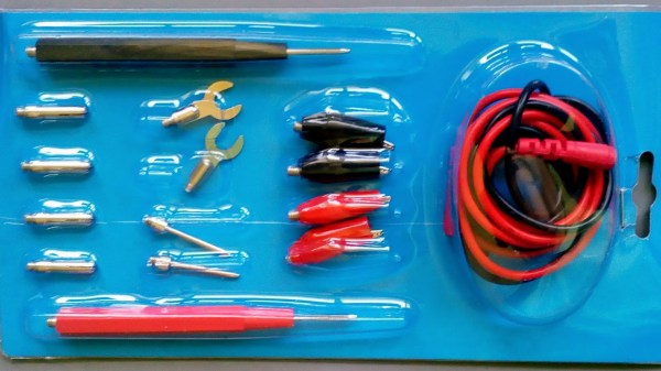
[Nop head] discovered that cheap multimeter leads costing only a few bucks can come with more than one may have bargained for. The first set had a large amount of useful-looking attachments, but the wires used for the leads were steel with a resistance of about one ohm each. With two leads in use, that means any resistance measurement gets two ohms added for free. More seriously, when measuring current, the wires can heat up rapidly. Voltage measurements would be affected the least, but the attachments and lead design expose a large amount of bare metal, which invites accidental shorts and can be a safety hazard with higher voltages.

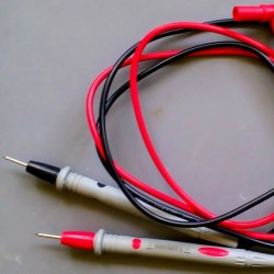
Are all cheap multimeter leads similarly useless? Not necessarily. [nop head] also purchased the set pictured here. It has no attachments, but was a much better design and had a resistance of only 64 milliohms. Not great, but certainly serviceable and clearly a much better value than the other set.
It’s usually not possible to identify garbage before it’s purchased, but [nop head] reminds us that if you do end up with trash in hand, poor quality counterfeits can be good for a refund. That goes for electronic components, too.

PCBs Without Any Substrate

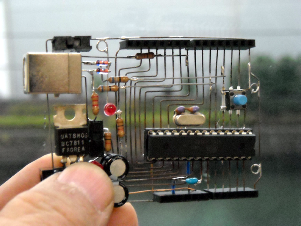
[Kimio Kosaka] is taking the concept of free-formed circuits to the next level with O’Baka Project No.7. It’s a fully functioning Arduino board, without the board. The traces are there and provide all of the support for the rest of the hardware. You can imagine the fragility of the package so it won’t be a surprise to learn that O’Baka Project means ‘stupid’ project.

We don’t think this manufacturing process is completely worthless. The ‘board’ seen above looks quite interesting and might be a good idea when building a show-piece where you want the circuitry to be seen. [Kimio] describes the process he used to achieve this look. The first step is to design a single-sided circuit board; he used EagleCAD. After printing out the traces he used 0.46mm steel wire to trace out each connection. Now heat up that soldering iron – [Kimio] recommends using high-acid flux to ease the process of soldering to the steel.

We think this would nicely compliment projects like LED cubes that use the circuit itself as a support structure. See this Arduino alternative from several different angles in the video after the break.

Continue reading “PCBs Without Any Substrate”