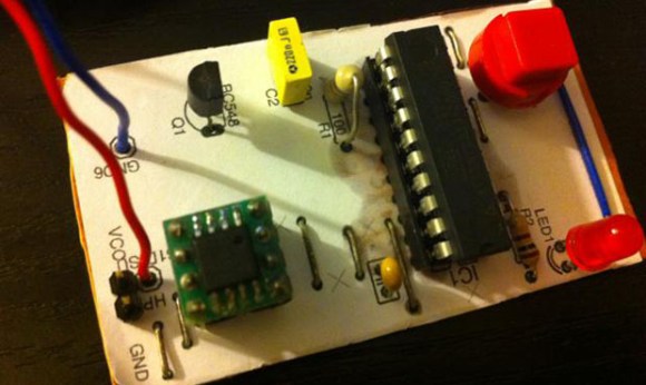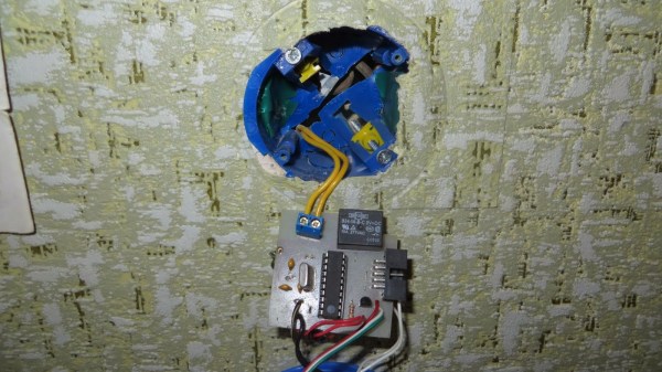
If you’re looking for your first electronics project, or a project to get someone else started in electronics, [Vadim] has you covered. Back when he was first starting out in electronics he built this infrared-controlled light switch that works with a standard TV remote control.
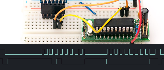
[Vadim]’s first few projects ended up as parts for other projects after they were built, so he wanted to build something useful that wouldn’t ultimately end up back in the parts drawer. The other requirements for the project were to use a microcontroller and to keep it simple. [Vadim] chose an ATtiny2313 to handle the RC-5 IR protocol and switch the light.
The circuit still has a switch to manually control the lights, preserving the original functionality of the light switch. The rest of the design includes a header for programming the board and another header for tying into the high voltage lines. This is a great project for anyone who knows what they’re doing with mains power but is just getting started with microcontrollers. If properly designed and implemented you’ll never stumble across a room to turn the lights out again!
Perhaps mixing high and low voltages on the same circuit board doesn’t spark your fancy or you can’t modify the light switch in your place of residence? Check out this mechanically-switched light switch.