Ploopy Builds Open Source RP2040-Powered Headphones And You Can Too!

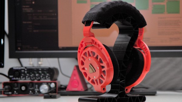
We’ve seen many DIY headphones projects on these fair pages over the years, but not many that are quite as DIY as the Ploopy Headphones. What makes this project interesting is the sheer depth of the construction, with every single part being made from what we might call base materials. Materials such as 3D printer filament, foam and felt, and the usual metallic vitamins.

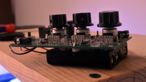
The electronics are fairly straightforward, with an RP2040 functioning as the USB audio interface and equalizer function. Audio samples are emitted as I2S into a PCM3050 24-bit stereo codec which generates a pair of differential output audio signals. These are then converted from differential to single-ended signals and passed on to the coil drivers. The coil drivers consist of no fewer than eight-paralleled opamps per channel. All of this is powered by the USB-C connection to the host computer. Whilst a kit of parts is available for this, you can make your own if you wish, as the full source (Altium designer needed for tweaks) is available on the Ploopy headphone GitHub.

A pretty ploopy response

Many DIY headphone builds would likely be using off-the-shelf speaker units, with large parts of the ear cups being taken from spare parts kits for commercial offerings. But not the Ploopy. The drivers are constructed from flex PCB coils with a standard TRRS jack on each side. Magnets for these coils to react against are held in a 3D-printed frame that is attached to the outer cover. The coils are aligned with a special jig and bonded to the ‘driver foam’ with some 3M VHB tape.

The ear cups are constructed with some 3D printed rings, foam pieces, and simple woven material. The resonator plates push into the inner side of the cup, and the assembly simply screws to the driver assembly. The incredibly detailed assembly wiki makes it look easy, but we reckon there are a few tricky steps in there to trip the unwary. The headband again consists of printed spring sections, some woven material, and foam with a few metallic vitamins thrown in. That makes it sounds simple, but it isn’t.

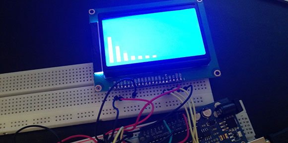
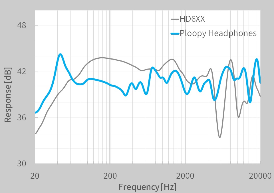
On the whole the build looks fantastic, but what does it sound like? The Ploopy team has tested them against a pair of Sennheiser HDRXX giving a broadly comparable response, but we’re no audio experts, and the proof, as always, is in the wearing. This project seems to be the ultimate in audio tweakability, with the punchy RP2040 capable of running six audio filters at the full 48 KHz, 16-bit audio, though, the PCM3050 is capable of more.

Want to build some headphones, but need a Bluetooth interface? We got you covered. Can 3D printed headphones ever compare to the big names? We’ll see.

A Graphic Equaliser The Analogue Way

There was a time when any hi-fi worth its salt had a little row of sliders on its front panel, a graphic equalizer. On a hi-fi these arrays of variable gain notch filters were little more than a fancy version of a tone control, but in professional audio and PA systems they are used with many more bands to precisely equalise a venue and remove any unwanted resonances.

On modern hi-fi the task is performed in software, but [Grant Giesbrecht] wanted an analogue equalizer more in the scheme of those fancy tone controls than the professional devices. His project makes for a fascinating foray into analogue filter design, as well as an understanding of how an equalizer combines multiple filters. Unexpectedly their outputs are not mixed because it proves surprisingly difficult to ensure all the filters have the same gain, instead they are in series with the signal path passing through all filters.

The resulting equalizer is neatly built upon a PCB with a 4-AA-cell power supply, and makes for a self-contained audio component. Unexpectedly such analogue equalizer have been few and far between here at Hackaday so it’s particularly pleasing to see. We’re more used to graphical displays for off-the-shelf devices.

An EQ Display For A Pedal Board

EQ

There are a lot of tinkerers out there who got their start in electronics with musical hacks. Surprisingly though, we don’t see many submissions to our tip line covering boost circuits for electric basses, rewiring guitar electronics, or even more complex effect pedals. [Deadbird], though, is bucking that trend with an EQ display stomp box that fits neatly on his pedal board.

[Deadbird]’s build isn’t a graphic equalizer that can change the volume of different frequency bands; instead, he used the MSGEQ7 chip to listen in on the signal his guitar is producing and display that on a 128×64 graphic backlit display.

The entire project was prototyped on a breadboard with an Arduino. After he got all the components working – a momentary switch to turn the pedal on and off, 1/4″ jacks for the input and output, and a power supply – [Deadbird] took an Arduino prototyping shield and made everything more permanent. Now he’s got an attractive pedal on his board that shows the signal coming from his guitar in seven neat bands.

Yukikaze, Music Visualizations

[youtube=http://www.youtube.com/watch?v=b4HtUwAkVDg]

[Taichi Inoue] put together this beautiful visualization system called Yukikaze, japanese for “snow wind”. Basically a spectrum analyzer, Yukikaze is delightful to watch. We would love to see what kind of response he gets, as most of the footage shows very slowly changing smooth jazz. While we don’t think he gets crisp EQ visualizations out of this since it is a single large chamber, we still think it is amazing to watch.

[via MakeZine]