Spying On The ESP32’s GPIO

The ESP32 has been a go-to microcontroller platform for a while now, thanks to its versatile capabilities, integrated Wi-Fi and Bluetooth connectivity, and low power consumption. It’s ideal for a wide range of projects especially those revolving around IoT, partially because of all of the libraries and tools available for it now. The latest tool from [The Last Outpost Workshop] adds a feature we didn’t know we wanted until now: a webserver showing real-time updates of what all of the GPIO pins are doing.

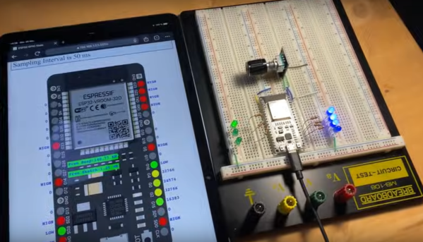
The live GPIO pin monitoring library sets up the ESP32 to stream information about what all of the pins are doing in real time to a webserver, which displays the information as a helpful graphic. The demonstration in the video below shows and example troubleshooting a situation where the code is correct but there’s a mistake in the wiring, helping to quickly identify the problem and hopefully eliminating a wild goose chase for a bug in the software. The library can be quickly installed using the Arduino IDE and only requires the use of one other library and a few lines of code to get everything up and running.

As far as a debugging tool goes, something like this could save a lot of us a significant amount of time, especially with how easy it is to set up. A real-time look into the pins and their behavior, including those set up for PWM, is invaluable for plenty of situations. Of course if you’re building something like a real-time operating system that needs responses within a very specific interval you may want to look at more in-depth strategies for probing the GPIO.

Thanks to [Bob] for the tip!

Continue reading “Spying On The ESP32’s GPIO”

Test PCBs On A Bed Of Nails

While it might be tempting to start soldering a circuit together once the design looks good on paper, experience tells us that it’s still good to test it out on a breadboard first to make sure everything works properly. That might be where the process ends for one-off projects, but for large production runs you’re going to need to test all the PCBs after they’re built, too. While you would use a breadboard for prototyping, the platform you’re going to need for quality control is called a “bed of nails“.

This project comes to us by way of [Thom] who has been doing a large production run of circuits meant to drive nixie tubes. After the each board is completed, they are laid on top of a number of pins arranged to mate to various points on the PCB. Without needing to use alligator clamps or anything else labor-intensive to test, this simple jig with all the test points built-in means that each board can be laid on the bed and tested to ensure it works properly. The test bed looks like a bed of nails as well, hence the name.

There are other ways of testing PCBs after production, too, but if your board doesn’t involve any type of processing they might be hard to implement. Nixie tubes are mostly in the “analog” realm so this test setup works well for [Thom]’s needs.

New Part Day: Better Pins

If you’re making a circuit that is designed to plug into a breadboard, you have a problem. Those 0.1″ header pins are square, and the metal leaf contacts inside a solderless breadboard will eventually get bent out of shape. You only need to look at the breadboards in a university electronics lab for evidence of this.

The solution to this problem is to make pins that are as similar as possible to the leads on DIP chips. They should be flat, of course, and it would be nice if they didn’t have those plastic spacers and didn’t present a blob of solder on the top side of the chip.

Flip-Pins are the answer. Think of them as standard pin headers, but meant for breadboard applications, and having a great aesthetic for your projects. They’re designed to look as much like standard IC pins as possible, and have the same thickness (0.020″) as standard DIP leads.

The application of Flip-Pins is a lot like soldering standard 0.1″ pin headers. The pins ship in neat little plastic retainers and can be tacked onto a PCB with just a little bit of solder. There’s a datasheet, and models for Altium, KiCad, and Eagle.

Flip-Pins grew out of another project, the OSHChip, to create an all-in-wonder chip containing an ARM microcontroller, radio, and a crossbar so any pin can be mapped to any peripheral. The OSChip itself is very cool, but one question constantly asked of the creator of this neat chip was, ‘where did you get those pins?’ From a factory. Now you can buy these pins from Evil Mad Scientist and Tindie. They’re a bit pricey, but they do look great.

Make Your Own Arduino Header Pins

There are two kinds of people in the world (and, no, this isn’t a binary joke). People who love the Arduino, and people who hate it. If you’ve ever tried to use a standard prototype board to mount on an Arduino, you’ll know what kind of person you are. When you notice the pins aren’t on 0.1 inch centers, you might think, “What the heck were those idiots thinking!” Or, you might say, “How clever! This way the connectors are keyed to prevent mistakes.” From your choice of statement, we can deduce your feelings on the subject.

[Rssalnero] clearly said something different. We weren’t there, but we suspect it was: “Gee. I should 3D print a jig to bend headers to fit.” Actually, he apparently tried to do it by hand (we’ve tried it, too). The results are not usually very good.

He created two simple 3D printed jigs that let you bend an 8-pin header. The first jig bends the correct offset and the second helps you straighten out the ends again. You can see the result in the picture above.

Continue reading “Make Your Own Arduino Header Pins”