Creating A Commodore 64 Cartridge On Single-Sided Stripboard

The DIY Commodore 64 cartridge. (Credit: Linus Åkesson)

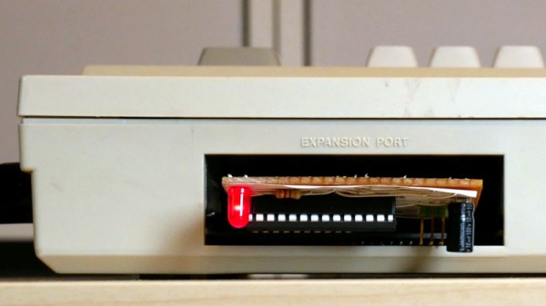
When you want to write software for a system like the Commodore 64, the obvious and safe choice is to create an image that can be used with a tape or floppy drive emulator. Yet these come with the obvious disadvantage of loading time and manual steps, much like with the original hardware. Unfortunately, if you crave that instant-on experience that cartridges offer – courtesy of them being plugged directly into the system’s CPU bus – you better get an EE diploma to figure it all out. Or maybe not, as [Linus Åkesson] found out when he created a custom cartridge to boot his Commodordian project from.

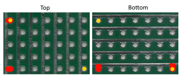
For the core of the cartridge a bit of stripboard was sufficient to interface with the C64’s cartridge slot. Despite being single-sided, all the required signals were on one side of the slot. These include the EXROM line that informs the system that a cartridge is present, the ROML line that informs the cartridge when the system is trying to read from it, and of course the data bus. After this the interaction gets somewhat interesting, due to the use of the single-sided stripboard, as the address bus and other signals are on the non-connected side.

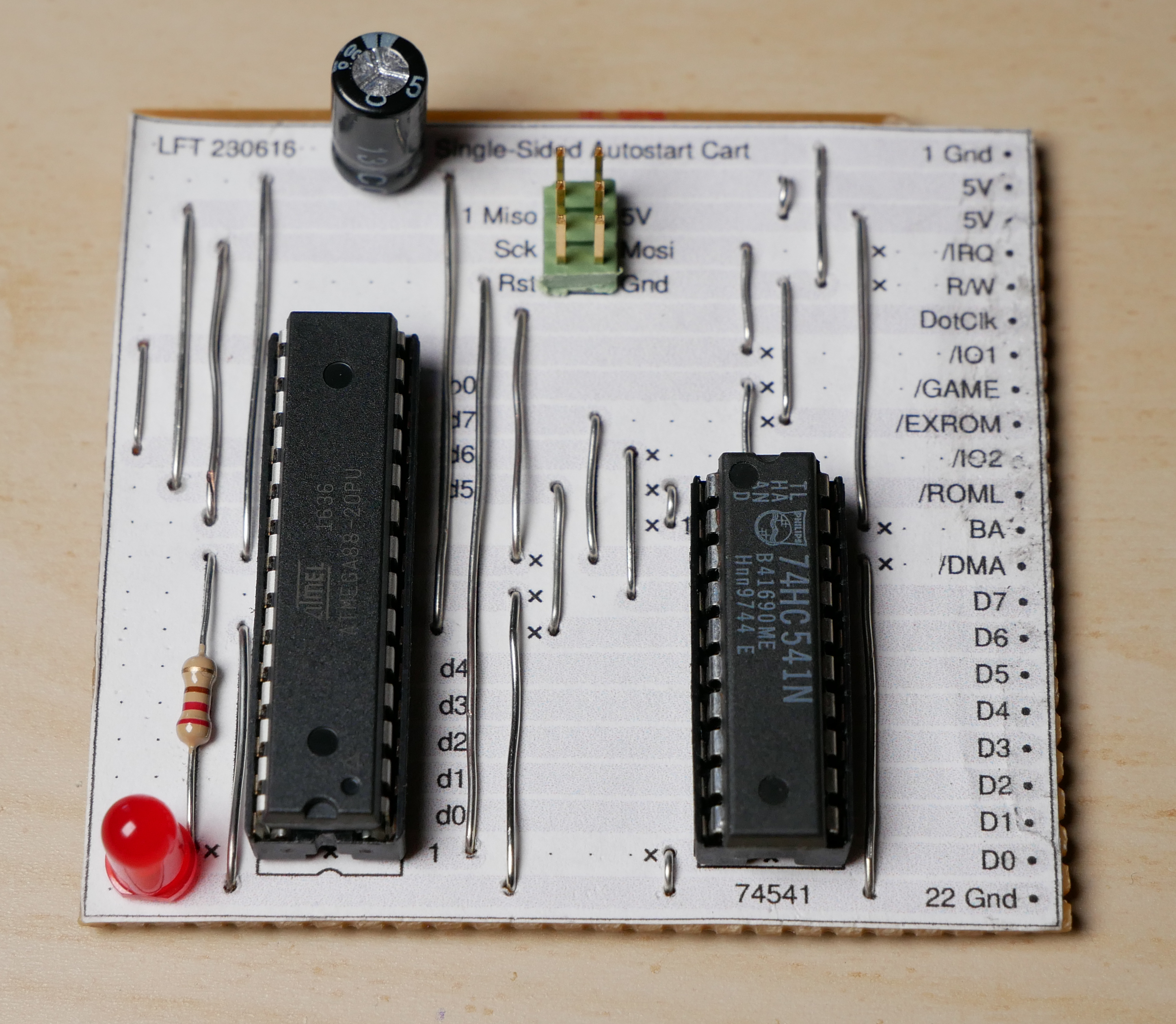
Working around this was the biggest challenge, but by creatively using the ROML and DotClk lines and by disabling the display output, the ATmega88 and 74HC541-based cartridge a working solution was created. There is still room for improvement here, naturally, but it would appear that if the goal is simply to autoload software on boot, this is definitely a workable solution. One could also splurge on double-sided stripboard, but that would strip away most of the fun of this solution.

Ask Hackaday: The Latest Advances In Perfboard

It’s no secret the Hackaday tip line gets a lot of email from Kickstarter campaigns and PR firms managing Kickstarter campaigns. Most of these are terrible products. Want a five-pound battery that can’t be recharged? Yeah, stuff like that.

Every once in a while, we come across a tip that’s a completely original idea. There’s a balance between ingenuity and practicality with these ideas, and I can’t figure out where this one sits. It’s a Kickstarter for perfboard, yes, but not like any perfboard you’ve ever seen.

Busboard, or solderable breadboard

Before we dig into this, let’s get some definitions straight. Perfboard is a sheet with holes drilled on a 0.1″ grid. The holes are plated on both sides, and each hole is an individual electrical node. Veroboard, or stripboard is a bunch of holes on a 0.1″ grid. These holes are also plated, but all the holes in a column are a single electrical node. You can cut the tracks between holes, but the basic idea here is to reduce the number of wires needed to connect components. Busboard, seen left, is a continuation of Veroboard, and is laid out like a solderless breadboard.

And so we come to the new invention, Perf+, the perfboard reinvented. This perfboard again is a series of plated holes on a 0.1″ grid. Alongside these holes is a plated bus. This bus does not connect to any hole; instead, a little bit of solder is used to connect it to holes on the same row or column. “Selective Veroboard,” you could call it.

Now for the real trick: on one side of the board, the plated busses run vertically. On the other side of the board, the plated busses run horizontally. This means any two holes on the protoboard can be connected as one electrical node simply with a bit of solder.

If ever there was an idea you could point to and simultaneously say, “that’s clever” and “I have no idea how to use this,” there you go. I’m pretty sure this idea isn’t better than a piece of stripboard, but it is different. If you have any idea of how to used this new, strange, and otherworldly protoboard for something useful, put a note in the comments.

Hackaday Links: August 17, 2014

hackaday-links-chain

[wjlafrance] recently picked up an old NeXTstation, complete with keyboard, mouse, display… and no display cable. The NeXT boxes had one of the weirder D-sub connectors a still weird DB-19 video connector, meaning [wjla] would have to roll his own. It’s basically just modifying a pair of DB-25 connectors with a dremel, but it works. Here’s the flickr set.

The guys at Flite Test put on a their first annual Flite Fest last month – an RC fly-in in the middle of Ohio – and they’re finally getting around to putting up the recap videos. +1 for using wacky waving inflatable arm flailing tube men as an obstacle course.

My phone’s battery is dead and my water pressure is too high.

Stripboard drawing paper, written in [; \LaTeX ;].

Remember the Commodore 16? [Dave] stuck a PicoITX mother board in one. He used the Keyrah interface to get the original keyboard working with USB. While we’re not too keen on sacrificing old computers to build a PC, it is a C16 (sorry [Bil]), and the end result is very, very clean.

A Chromecast picture frame. [philenotfound] had a 17″ LCD panel from an old Powerbook, and with a $30 LVDS to HDMI adapter, he made a pretty classy Chromecast picture frame.


Build A Bare Bones Arduino Clone Which Maximizes Its Use Of Real Estate

barebones-arduino-clone-at-home

Check out all the stuff crammed into a small swath of strip board. It’s got that characteristic look of a roll-your-own Arduino board, which is exactly what it is. [S. Erisman] shows you how to build your own copy of his YABBS; Yet Another Bare Bones Arduino (on Stripboard).

The strips of copper on the bottom of the substrate run perpendicular to the DIP chip and have been sliced in the middle. This greatly reduces the amount of jumpering that would have been necessary if using protoboard. A few wires make the necessary connections between the two tooled SIL headers that make up the chip socket. On the right hand side there a voltage regulator with smoothing caps. The left side hosts the obligatory pin 13 LED, and the crystal oscillator can be glimpsed on the far side of the ATmega328.

Pin headers along either side of the board have been altered to allow for soldering from the wrong side of the plastic frames. Note that there’s a three-pin hunk that breaks out the voltage regulator, and an ISP programming header sticking out the top to which those female jumper wires are connected.

Ringing in at as little as $2-$4.75 a piece you’ll have no problem leaving this in a project for the long hall. We can’t say the same for a $30+ brand name unit.

Hand Soldering BGA Parts Should Be A Circus Act

Okay, we think it’s questionable when people say they have no problem soldering QFN packages, but BGA? Granted this chip has far fewer balls on it than many, but it’s still quite impressive that [Xevel] was able to solder this BGA breakout by hand.

The chip you see above is a TMP006 infrared temperature sensor from TI. [Xevel] picked up the part but didn’t want to break the bank when prototyping by buying a proper PCB to host it. There are only eight conductors on it, arranged in a grid with 0.5mm pitch. That didn’t seem to scare him off, as the video after the break shows him connecting each to a conductor on a hunk of stripboard.

[Xevel] mentions that this is a dead-bug style project. Usually you glue the part upside down when using that technique, but it needs line of sight to get an accurate temperature reading so he first cut a hole in the substrate. We’d bet he’s using wire-wrapping wire to make the connections. It’s a very fine solid core wire which is perfect for this kind of work.

Continue reading “Hand Soldering BGA Parts Should Be A Circus Act”

Cheap And Cheerful Arduino Breadboard Basics

For those less experienced folks looking to move their Arduino projects to more permanent installations, this is just for you! [Martyn] Posted a three part series, VeroBoardUino, over at his blog about moving your Arduino project to a soldered breadboard.

Part one kicks off with the appropriate breadboard requirements, modifications, and a simple 7805 power supply. In the guide [Martyn]  is using strip board, so copper connections will have to be broken using a drill or just by scraping with a hobby knife. Strip board also saves a bit of wire routing in the end. Part two handles the reset button, serial connection and chip socket  (Part 2.5 has also been added to include schematics of the breadboard). Finally, part three installs the crystal and connects your Atmega chip to power and ground.

Next post he will be covering more on the software end of things, burning the bootloader and uploading programs to your new board so stay tuned for updates!

Stripboard Drawdio

drawdio

When we posted about the Drawdio release, mentioned how simple the circuit was and that we wouldn’t be surprised if people adapted it. [Dylski] decided to build it using stripboard and parts he had laying around. He shows how he laid it out on paper so that it would fit on a 29×5 piece. It took some planning, but the end result is a perfectly functional as you can see in the video below. Continue reading “Stripboard Drawdio”