Resistance In Motion: What You Should Know About Variable Resistors

Adjusting the volume dial on a sound system, sensing your finger position on a touch screen, and knowing when someone’s in the car are just a few examples of where you encounter variable resistors in everyday life. The ability to change resistance means the ability to interact, and that’s why variable resistance devices are found in so many things.

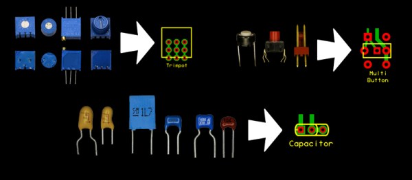
The principles are the same, but there are so many ways to split a volt. Let’s take a look at what goes into rotary pots, rheostats, membrane potentiometers, resistive touchscreens, force sensitive resistors, as well as flex and stretch sensors.

Continue reading “Resistance In Motion: What You Should Know About Variable Resistors”

Design In Package Flexibility Into Your Next PCB

To err is human.  And to order the wrong component foot print is just part of engineering. It happens to us all; You’re working hard to finish a design, you have PCBs on the way and you’re putting in your order into your favorite parts supplier. It’s late, and you’re tired. You hit submit, and breathe a sigh of relief. Little do you know that in about a week when everything arrives, that you’ll have ordered the wrong component package for your design.

Well, fear not. [David Cook] has a solution that could save your bacon. He shows you how to design multiple footprints into your board to avoid the most common mistakes such as voltage regulators with different pin-outs than expected. Other uses for the trick include, common trim pots with different pin spacing and a layout for decoupling caps that will fit both a 0.1″ and 0.2″ footprints.

We’ll file this under the “Why Didn’t I Think of That” category. It’s a super simple hack, but that’s what we love about it. We could see this being very handy for people who often scavenge parts. Also, for makers that sell just a bare PCBs (without parts) to those that want just a board. No, it won’t save you if your need an SMD and you mistakenly ordered a dip, but at the end of the day, it’s a nice trick to keep up your sleeve.  You might never know when you’ll need it.

Hi-Hat MIDI Controller

midi-hi-hat-controller

Drumming hackers take note, if you’ve got an extra bass drum pedal it’s cheap and simple to use it as a MIDI controller. This rig was thrown together to supplement a DIG DRUM electric drum set. That piece of equipment has a pedal add-on that didn’t come with it. Turns out all it does is feed a resistance value to the set.

To get this up and running a frame was built from a metal base and acrylic side piece. The acrylic hosts a trimmable potentiometer which connects to an 1/4″ stereo jack right beside it. This facilitates connecting the pedal to the drum set using an audio patch cable. Interface with the pedal is accomplished with a few bits from the hardware store. The axle of the pedal sticks out one side, and is clamped between two washers. The other side of the washer grip the timpot causing it to move when the pedal does.

This hardware is a snap to use with your own MIDI device. We’d suggest giving the HIDUINO package a try.

Ask Hackaday: What’s An Easy Way To Build A Potentiometer For A Soldering Iron?

diy-potentiometer-2

[Lee] wrote in to share the work he’s done in building a controller for his soldering iron. The idea started when he was working with an ATX power supply. He figured if it works as a makeshift bench supply perhaps he could use it as the source for an adjustable iron. To get around the built-in short-circuit protection he needed a potentiometer to limit the current while allowing for adjustments. His first circuit used a resistor salvaged from an AT supply and a trimpot from some computer speakers. That melted rather quickly as the pot was not power rated.

This is a picture of his next attempt. He built his own potentiometer. It uses the center conductor from some coaxial cable wrapped around the plastic frame of an old cooling fan. Once the wire was in place he sanded down the insulation on top to expose the conductor. The sweeper is a piece of solid core wire which pivots to connect to the coil in different places. It works, and so far he’s managed to adjust a 5V rail between 5A and 20A.

How would you make this system more robust? Short of buying a trimpot with a higher power rating, do you think this is the easy way to build a soldering iron controller? Let us know by leaving your thoughts in the comments.

Continue reading “Ask Hackaday: What’s An Easy Way To Build A Potentiometer For A Soldering Iron?”

LEGO Wah-wah Pedal

Here’s a guitar wah-wah pedal that [Christian Munk] built. Inside you’ll find a circuit board that he etched and populated based on this design but he chose to build the housing out of LEGO. The video after the break gives you an idea of what it sounds like, but for those who’ve stepped on a LEGO piece with bare feet, his pedal pounding might make you cringe!

To manipulate the sound the pedal rocks forward and backward on a center pivot shown above as a grey “nut” sticking out the side of the frame. Inside there’s a system of LEGO gears that turn a trimpot to alter the sound. This might go along nicely with that guitar amp you hacked together.

Continue reading “LEGO Wah-wah Pedal”

Crossfade Curve Tweaking

Tired of the disappointing performance from the crossfader on his Numark MIXDECK, [dj JD] cracked it open and made the crossfade curves adjustable. It’s a super-simple hack that just introduces two 100k trimpots to the crossfade slider. The change led to a higher volume level on the current channel until the slider was much nearer to the center. The added adjustment feature might be nice to have as two more knobs on the board but [JD’s] method leaves his equipment with a stock appearance. Is this a more refined version of circuit bending?