
Our initial view of the Spy Video TRAKR “App BUILDR” site had us believing this would be an internet-based code editor and compiler, similar to the mbed microcontroller development tools. Delving deeper into the available resources, we’re not entirely sure that’s an accurate assessment — TRAKR may well permit or even require offline development after all. Regardless of the final plan, in the interim we have sniffed out the early documentation, libraries and standalone C compiler and have beaten it into submission for your entertainment, in order to produce our first TRAKR hack!
TRAKR software development at the moment, to phrase it just as politely as we can, has a Wild West flavor to it. The finished tools and reference materials aren’t expected until October. Early documentation is rough — entire sections still missing — so it’s frequently necessary to rummage through their example code to learn how things operate. And the compiler is exceedingly rough right now…it requires a minor patch just to get started, and works only within Cygwin, a UNIX-like command shell for Windows systems. So tonight we’re gonna program like it’s 1999! To continue, we’ll have to assume you’re at least vaguely familiar with command-line development tools, as explaining the entire process from scratch is more than we can fit here.
It probably goes without saying, but for posterity: these are beta tools and the entire process will almost certainly change as the TRAKR HAKR site nears release, rendering these directions obsolete. Until then, for those wanting to get an early start, here’s how we began building our own TRAKR hacks…
Getting the compiler
The C compiler and documentation are presently located on the Apps Help page of the TRAKR web site. Just follow the directions there to download the App Primer (containing the compiler and demo source code), the TRAKR Codebook PDF (an introduction to TRAKR programming), and the Function Reference and code snippets for lighter-weight reference once you’re familiar with the concepts.
The Apps Help page states that the tools work with Linux, but this isn’t entirely true. The App Primer ZIP file contains only the Cygwin (Windows) toolchain, along with the TRAKR libraries and sample code. The C compiler is based on arm-elf-gcc 3.4.6 — Linux users might stand a chance with the pre-built 3.4.3 package from the GNU ARM web site. You’ll still need to download the App Primer for the libraries. With Mac OS X, things get ugly…we’ve yet to locate a viable package for Intel Macs. Building the 3.4.6 toolchain from source (or via MacPorts) has brought only frustration, and the TRAKR makefiles don’t play nice with later (but working) arm-elf-gcc editions. Joy. Eager to move ahead, and not wanting to invest a lot of time on beta tools that are certain to change, some of us are simply using the Windows package in VirtualBox for now.
Getting the compiler to actually work
After unpacking the App Primer ZIP file, copy the TRAKR.1 folder inside to a suitable working location within your Cygwin directory. The _MACOSX folder can be deleted — this is just an artifact of the files having passed through a Mac at one point; there are no OS X build tools here.
Just unpacking the Primer and trying to compile the examples, you’ll encounter a slew of “undefined reference” error messages and a failed build. There’s a problem with the TRAKR library — some test data that’s not properly archived — but it’s a straightforward fix. Go into the Internals directory and edit the Makefile using vi (or another editor of choice if you have one installed). Line 22 looks like this:
OBJECTS = $(S_OBJECTS) $(O_OBJECTS)
It should be changed to this:
OBJECTS = $(S_OBJECTS) $(O_OBJECTS) $(O_IMAGES)
Save the changes and exit the editor, then (still in the Internals directory) type:
make trakr.a
Now you can go back to any of the examples and successfully compile by typing “make”. For example:
cd ../EX06_Sound
make
This will create a “.bin” file that can be loaded onto the TRAKR. Attach a USB cable between your computer and the TRAKR vehicle (the power switch can be on or off, it doesn’t matter). In a moment, the TRAKR’s internal storage will show up as a small removable drive. Then just copy the .bin file to the APPs folder on this drive, e.g.:
cp EX\ Sound.bin E:APPs
Disconnect the USB cable, power up the TRAKR and remote, press the remote’s Home button and use either stick to navigate to the “EX Sound” menu item, then press the “Go” button. The app should prompt you to record 10 seconds of audio from the TRAKR’s microphone, then plays this back. Cool stuff!
Writing your own apps
Each TRAKR app is required to have three functions: Start(), Run() and End(). Your Start() function contains one-time initialization code, such as opening the motors to software control; End() is the complimentary function for when your program finishes, restoring control to normal TRAKR operation. Run() contains the meat of your application…this function is expected to return either “true” or “false” to indicate whether it should run again iteratively, or is ready to exit.
The header file svt.h contains constants and prototypes for the functions described in the Codebook and reference documents. This includes high-level functions for producing graphics and sound, turning the infrared LED on or off, reading the controls, driving the motors and accessing the SD card. This is all the Official Documented Stuff thatApp BUILDR will encourage us to use.
But there’s a second header, JAPI.h, revealing much of the underlying functionality on which the TRAKR library is built. And for the time being, this is the only way to access the really interesting stuff like digital I/O, video processing and USB host. This is most definitely not the Official Documented Stuff, and relying on it now means your code will probably require some changes to work with the Official Stuff later.
There’s something conspicuously absent from both libraries: higher-level digital I/O such as serial UART or precise PWM control. We’re not even certain yet whether any the accessible breakout lines correspond to these hardware functions. Maybe it’s something forthcoming, or maybe this will require the chip datasheet, with code talking to the registers directly. Worst case, such I/O will just have to be done with slower bit-banged methods. Which is exactly what we do with…
Our first hack
We really wanted to showcase both the software and hardware hackability of the TRAKR. There isn’t the space for an overly-technical writeup, but neither do we want to send you off with a trivial modification. Hopefully we’ve found a good balance here…mildly esoteric, but most readers with modest prior soldering and programming experience should be able to follow along and create something similar.
Our inspiration came from an earlier Hack a Day article about the txtBomber, a handheld dot-matrix graffiti printer:
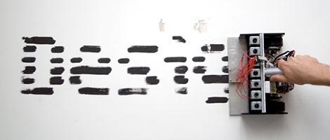
The width of the TRAKR is about the same as a sheet of paper. With a row of solenoids and some paint markers, we could make a fantastic mess with this…or even simpler, skip the markers and head to the beach, having the TRAKR “comb” messages in the sand.
Problem is, we didn’t have a stack of solenoids on hand, and we wanted to get right into this rather than wait around for parts to arrive. Rooting among the detritus of our secret underground vault, we found a great substitute from a prior project: a row of 48 addressable LEDs driven by shift registers, the board on which they’re mounted perfectly matching the TRAKR’s 10 inch width! So our aim now was to achieve the same effect in light. The TRAKR moves too slowly for retinal persistence of vision to occur, but we could use long exposure photography to capture the results.
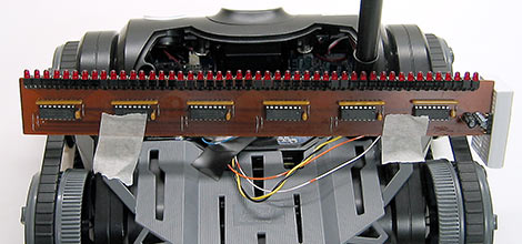
Anyone can buy a TRAKR off the shelf now, but the light bar was something custom-made for a POV project. The good news is that it’s a very common circuit, something we’ve linked to before, and a slightly scaled-back version can be built on a breadboard. Ours has a set of six 75HC595 shift registers with decoupling caps, each driving eight LEDs with associated current-limiting resistors. Very similar to what’s shown in that article, but cascaded out to six chips. You could also do something similar (and way more colorful) using ShiftBrite LEDs.
The LED board is held to the ’bot with masking tape. Spared no expense!
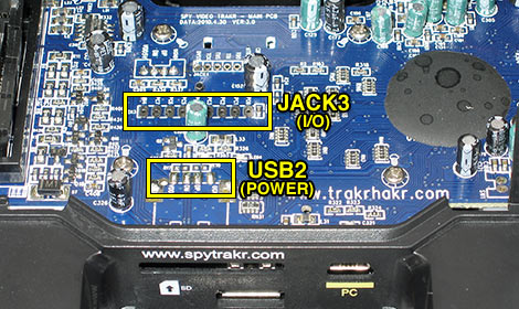
As pointed out in our teardown, the all-important JACK3, containing the GPIO lines, is smack dab in the middle of the TRAKR main board. The unpopulated header USB2, which we’ll use as a power tap, is closer to the outside edge.
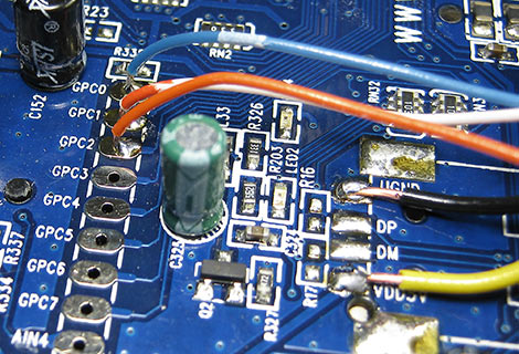
In our haste to create a presentable demo, we just soldered wires directly to the TRAKR’s circuit board, but at some point intend to dismantle the thing again and solder on a proper header for inserting wires. For +5VDC and ground, the VDD5V and VGND pads of the idle USB connector are used. The shift registers require three data lines (as we’ll explain in a moment), and we opted to use the first GPIO lines on the board, labeled GPC0, GPC1 and GPC2.
The shift register interface, referred to as a 3-Wire serial connection or sometimes SPI (Serial Peripheral Interconnect), is a synchronous serial interface, meaning that each bit of data is accompanied by the synchronized tick of a clock bit on another line. A third line, called the latch, signals the end of the data transmission — in the case of an 8-bit shift register, this will output on its 8 parallel data lines the last 8 bits that were “clocked in” over the serial connection.
For our light bar hack, we’ll use GPC0 as the clock line, GPC1 as the data line, and GPC2 as the latch. Most microcontrollers feature some kind of native 3-Wire/SPI support, but as mentioned earlier, with the TRAKR library at present we’ll have to trigger all these bits through software control.
Next thing we need is an image to display on the LEDs, one row at a time. Naturally, we’re going to use the Hack a Day logo:

In the source code archive provided later, the image is present as a 1-bit Windows BMP file, simple to work with because the data is uncompressed. The image is turned sideways as it requires less code for the program to decode each horizontal row of the bitmap than it would for processing vertical columns. It’s 48 pixels wide, corresponding to the 48 pixels in the LED bar, and 60 pixels high, including some blank lines at either end so repeated logos don’t run one into the next.
Our example program is hardcoded for this one demo image, which is embedded in the executable. A more sophisticated program might allow the user to load an image from the SD card, and would properly parse the BMP header to query the actual image dimensions. Again, we’re just looking to keep the code simple and not stretching out to hundreds of lines.
// POV demo for Spy Video TRAKR w/shift register LED bar.

#include "svt.h"  // Official API
#include "JAPI.h" // Secret sauce

#define ROWS  60 // Image height in pixels
#define COLS  6  // Image width in bytes (pixels = 8x this)
#define PAD   (3 - ((COLS - 1) & 3))
extern unsigned char _binary_logo_bmp_start[]; // In logo.o

#define CLOCK (1 << 0)  // GPC0
#define DATA  (1 << 1)  // GPC1
#define LATCH (1 << 2)  // GPC2

void Start()
{
  JAPI_SetIoOutputMode(CLOCK | DATA | LATCH);
}

bool Run()
{
  unsigned char *ptr, byte;
  int r, c, b;

  // 62 byte offset to start of image data within BMP:
  // 14 byte BMP header, 40 byte DIB header, 8 byte palette
  ptr = &_binary_logo_bmp_start[62];

  for(r=0; r<ROWS; r++) {     // Each line in image
    for(c=0; c<COLS; c++) {   // Each byte in line
      byte = *ptr++;
      for(b=128; b; b>>=1) {  // Each bit in byte
        if(byte & b) JAPI_SetIoLow(DATA);
        else         JAPI_SetIoHigh(DATA);
        JAPI_SetIoHigh(CLOCK);
        JAPI_SetIoLow(CLOCK);
      }
    }
    JAPI_SetIoHigh(LATCH);
    JAPI_SetIoLow(LATCH);
    Sleep(20);
    ptr += PAD;  // BMP rows start on 4-byte boundary
  }

  return true;
}

void End()
{
}
The graphics-related #defines should be clear by now, we know this program is set up for this one specific image. The CLOCK, DATA and LATCH #defines correspond to the individual bits passed to GPIO-related functions, making subsequent code easier to read.
In the Start() function, the call to JAPI_SetIoOutputMode() initializes all three lines as outputs.
Because of the way the image is formatted, there’s minimal work now to be done in the Run() function. For each horizontal row of the image, six bytes of image data are output one bit at a time, 48 bits total: the DATA line is set either high or low to indicate the corresponding 1-bit pixel value, and then the CLOCK line is quickly toggled high and then low to “clock out” the data bit. At the end of each row, the LATCH line is similarly toggled to tell the shift registers to display the new data. A 20 millisecond delay holds the image for a moment so it’s not all scrunched together, given the TRAKR’s limited speed.
The next line advances the image pointer to the start of the next row, if required. In BMP files, rows are always a multiple of 4 bytes wide. Our bitmap is only 48 pixels (6 bytes) across, so this skips the two extra bytes at the end of each row. The final “return true;” line tells the TRAKR library to repeat our Run() function again indefinitely.
The End() function is empty for this program, but it still needs to be present to keep the linker happy.
A ZIP file containing the above source code, bitmap image and makefile can be downloaded here. Extract this archive within the Trakr.1 folder, alongside (not within) the Internals directory. “cd” to this directory and type “make”. If all goes as planned, this should produce the file POV.bin, which can be loaded on the TRAKR as described earlier.

Something to consider when hanging circuitry off the TRAKR is the proximity to the 2.4 GHz antenna. We wasted a good half hour tracking down a “software bug” that in reality turned out to be our sloppy, long wires picking up radio interference (you can still see a few whacked-out pixels in the image above). Keep wire runs as short as possible, perpendicular to the antenna.
Bright future
Even in this early stage, warts and all, we’re quite excited by the prospects for this toy’s hackability. Wild Planet is to be applauded for their open-minded approach in encouraging software and hardware modifications. A lot of comparisons are already being made to the Roomba and Rovio, both of which have spawned enthusiast sites and even books. Time will tell if the Spy Video TRAKR catches on the same way.
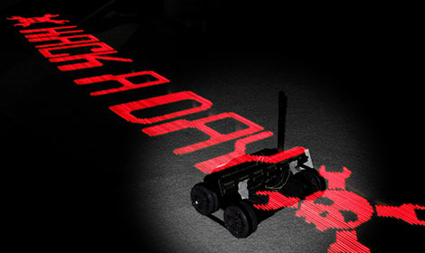
So that’s our TRAKR hack…now let’s see yours! When you’ve got something cool to showcase, don’t forget to tip us off!


Awesome job, you guys have been so detailed in this project!! It’s nice to see the HAD logo all over this hack.
Great hack, nice code, good outcome. Great Work!
Great job. I used a different method to control the GPIOs. I defined the following structure:
// Trakr Ports file
// Port control register struct
typedef struct
{
unsigned int OMD; // Output mode a 1 causes a pin to be an output
unsigned int PUEN; // Pullup enables
unsigned int DOUT; // Output data
unsigned int PIN; // Actual pin states
} sPort;
// GPIO Base address
#define GP_BA 0xfff84000
#define PORTC (*(sPort *)(GP_BA+0x20)) // Port C control registers (offset of 0x20)
So to write out data you would just:
PORTC.DOUT = 0x42;
Also I noticed a couple of things while playing around with the software. If you are running an app from the SD card when you exit it the menu no longer shows apps on the card. I tracked that down to a bug in the trakr.c file in Internals.
The function SVT_Log_Close() doesn’t close the file system. Just add a call to SVT_FileSystem_Close(); and that fixes it.
You don’t need to include the image dir for the missing image objects, they are only used in the test.c app in the internals dir and if you remove the refs to image0, etc. from svt.c and svt.h you no longer need thoses object files.
Last thing (I promise) be careful using the 5V supply with the GPIO pins, those are 3.3V I/O’s and could be damaged by a 5V signal. The same goes for the AIN4 pin. (Which works great, gives a value from 0 to 1023 with 0-3.3V in)
Sorry for the long post. Thanks again for the great work!
Joe C.
Why was my last post deleted?
Sorry, It’s back now, please ignore previous post!
Really REALLY great stuff! I wish I had the time and skills to explore this sort of hack. My spare roomba is still sitting waiting for a project. Congrats to you (and Joe C.) for pioneering this new platform!
something i’d like to see done yet i don’t have the time/knowlege/resources to do it:
remember this hack?
http://hackaday.com/2010/08/04/racing-game-uses-a-physical-race-track-and-vehicle/
well you could do something similar
i would like to see two of the trakrs in a physical arena built like the old ‘tank’ arcade
you could attach an old laser tag game on it for the firing/points (limit the firing to once every 5 sec or something). once someone scores you could program it to go back to their starting possition
also it would be cool if it were playable online
…would be pretty awesome
This is awesome, great work on the hack and great documentation!
If you want to hardcode images into C, there’s actually a really easy way to do it. GIMP can save images in .c or .h formats, containing an array with the image data and macros for retrieving pixel data. It can also save in PNM, PGM, and PPM formats which are very simple ASCII (and highly inefficient) formats, which can either be used as easy to process image files, or piped through some custom conversion to include in your code.
You guys ROCK
I want one of these things so f’ing bad…
I’ve modded my Trakr to have a 10 pin socket for expansion. It gives access to PORTC and AIN4. (I combined GPC7 and AIN4 to get it into 10 pins w/power and ground. I built up an AVR board for servo control, and I’ve got code running on the Trakr that programs the AVR from a hex file on the SD card using SPI. Now I’m working on the servo code for the AVR. In the end I’m hoping to build some sort of remote manipulator arm for it.
If there is any interest I’ll post pics/schematics/code.
Joe C.
thanks Joe C .. .. I hope to Know if you Con help me in Some advice about how can i connected and integrated Some device to robot to introduce service robot .. . iam beginner in this Field
Since my trakr isn’t here yet, i ran API_LIBs.o through IDA. All these calls are SVC calls to fn. 0xF0 or 0xF1 with R1=fn.#, R2=SP (where r0-r3 from call are put) and R3 looks like a check code: 0xA1BFF5CD for every call. Making a list to post later..
I just want to point out that if you go into Trakr.1/Internals you can read every command the trakr can recognize you could even recreate the entire trakr operating system if you wanted to plus you could add adjustments.
awesome now I REALLY NEED ONE!!!!!!!!!!!!! could you send me one to “review?”
Great info here!
Thanks from a new owner. (just scraped the crummy sticker off the front)
^ JOE C. if your reading I just got a trackr and would love to see your mods and servo code. I am a noob on MC programming and this would give me a great start.
for my first project I want to motorize the camera….
Hey Guys,
Nice Work Joe C.
please keep posting, your stuff is great!
C:\Trakr\pov>make
Hi All,
I get the following error when I try to compile the code in POV.ZIP
is there a file missing?
Compiling app.c
Linking…
Creating file Intermediate/Sample.elf…
./Intermediate/app.o: In function `Run’:
/cygdrive/c/Trakr/pov/app.c:50: undefined reference to `_binary_logo_bmp_start’
collect2: ld returned 1 exit status
make: *** [Intermediate/Sample.elf] Error 1
C:\Trakr\pov>
Does anyone know how the range can be improved? I would like to get a little more distance out of mine. Maybe even adding more IR LEDs to see a little more distance in the dark.
Please I need knew what type of this robot controler?
I have a Trakr and remote for sell.I dont know anything about it.When I turn it on The only message I get is No Signal.If someone knows how to get it going and wants it,Ill make You a good deal on it.My name is Billy My phone number is 925-812-3273