ATtiny Hacks: Robot Halloween Costume

When it comes to Halloween costumes, [Michael] doesn’t like buying expensive and poorly made bits of cloth and fabric that resembles [random Disney character]. Last year, his son decided to be a robot for Halloween and although gray spray paint and dryer vent hose make a very good costume, that only goes so far. The robot needed lights, so [Michael] spent a little time on this build that blinks a few LEDs in a random pattern.

The build is very simple; an ATtiny13 drives two 74HC595 shift registers. The code – all 30-odd lines of it – uses the random() function to shift high or low values to the shift registers. After pausing for a little bit, the cycle continues and a new patterns of LEDs light up.

The electronics of the robot costume could be easily transferred to another theme – astronauts need LEDs on their backpack, and of course aliens communicate with blinking lights. In any event, it would avoid last year’s fiasco with a dozen [Heath Ledger] Jokers. Check out the video of [Michael]’s intergalactic robot son after the break.

Continue reading “ATtiny Hacks: Robot Halloween Costume”

ATtiny Hacks: ATtiny10 Game – Doing More With Less

ATtiny Hacks Theme Banner

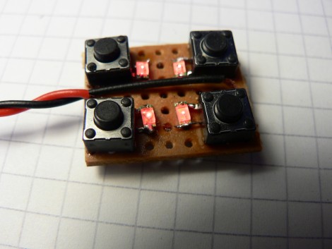
Okay, you’ve got a six-pin microcontroller with 1k of program memory, 32 bytes of SRAM, and it can’t be programmed using an In-System-Programmer. Do you think you can use it to develop a game? [Wrtlprnft] managed to build a Simon Says game based on the diminutive device that has four buttons and four LEDs. Judging from the video after the break, we’d say he nailed it!

There are so many design challenges here. First off, with only six pins total getting eight devices connected and working means doubling up on each I/O pin and using the reset pin as a doubled-up I/O. We’ve seen momentary push buttons on the same pins as LEDs before, so that’s not too hard to get working.

But if you’re using the reset pin how do you flash the thing? It doesn’t use the same ISP programming protocol that it’s bigger cousins do, so [Wrtlprnft] used an ATmega1284P to program it, hooking up to the three I/O pins and using a transistor to push 12V on the reset pin. But there’s still the matter of writing the code. It has half of the 32 registers you’d expect to find. He ended up ditching C and went straight to writing Assembly because of the diminished instruction set. It’s the first thing he’s written in Assembly, and a great way to learn the ropes.

It may not be as polished, but we do like it just as much as the Karate Chop Simon Says game which has a lot of other bells and whistles.

Continue reading “ATtiny Hacks: ATtiny10 Game – Doing More With Less”

Octocopter Will Someday Kill Someone

Above you can see Doctor Wily a Chinese hacker starting up one of the propellers on his octocopter. It seems that the man is using a collection of eight motorcycle engines, each with its own wooden propeller to create an eight-bladed helicopter. We were able to locate some video footage of his experiments, which you’ll find embedded after the break. As you can see, this is perfectly capable of flight, but we’re not quite sure if we’d call it controlled flight just yet.

The video starts off showing all kinds of hack-ity activities, like tightening the bolts on the propeller and priming the gas lines by sucking on them like a straw (mmmm….. high-octane!). Coke bottles serve as the gas tanks, and you’ll want to keep your hands inside the vehicle because there’s no cages to keep them out of the hand-started propellers. Although we don’t speak his language, we did understand the demonstration of the controls that the man gives, showing an earlier model with rings of fabric around four of the propellers meant to help direct the downward thrust as a steering mechanism. We don’t think this will be viable until there is some type of PID system that predicts the performance of each motor and makes quick adjustments to keep the craft balanced. None-the-less we were glued to the screen hoping that this turkey would fly.

Continue reading “Octocopter Will Someday Kill Someone”

USB Stick Propeller Development Board

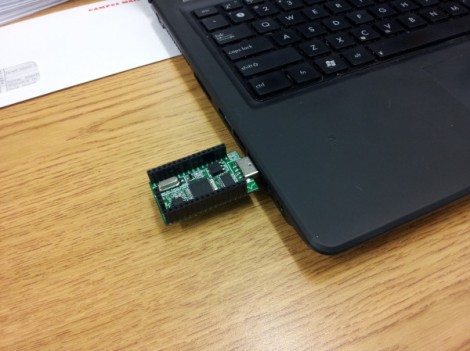
[Parker Dillmann] is nearing the end of the prototyping process for his Propeller development board. He wanted a tool that let him work on projects without the need for a bunch of equipment, while still maintaining the ability to extend the hardware when necessary. His last dev board used a large piece of protoboard to host through hole components including the Propeller chip, 3.3V and 5V regultors, an SD card reader, and female pin headers. This version migrates to a PCB from a fab house and mostly surface mount components.

He decided to use a USB-stick design having been happy with some of TI’s prototyping tools. The Parallax branded development boards use an FTDI 232RL chip for easy programming and that’s what he’s gone with as well. A P8X32A chip in the QFP package was chosen for easier soldering than the smaller QFN option. There’s also a 64kb EEPROM on board to give you plenty of room for your SPIN programs. All the pins are broken out to DIL female headers and there’s a power header on the end opposite the USB plug. [Parker] plans to do a bit of testing to make sure there’s no problems with signal routing below the 5Mhz crystal footprint. This run of prototypes came from the Seeed Studios Fusion PCB servcie–he got more than 10 boards for a total of $13… that’s almost unbelievable.

Add Some LED Enhancement To Your Netbook Lid

[Mathieu] needed to open up his Acer Aspire One to do a hard drive replacement and decided to add a bit of pizzazz while he was in there. The image above is the lid of the netbook adorned with RGB LEDs and a spray painted stencil.

He previously purchased a set of surface mount RGB packages on eBay and thought that they were perfect for this hack. after removing the case he found that by using a flex PCB he would be able to fit the LEDs inside, and pass the connections through to the main computer housing. The leads connect to a Teensy board, which is held in place with a liberal application of hot glue. [Mathieu] removed the USB connector and soldered jumper wires to one of the computers ports. In the video after the break you can see that he uses the programming software to write some code to the Teensy, driving the LEDs. We’d like to see it set to listen for serial communications and react accordingly. That way you could use it for notifications, as an audio VU meter, to track torrent progress, etc.

Continue reading “Add Some LED Enhancement To Your Netbook Lid”

Flip Off Your Alarm Clock!

flipclock

[Corbin] hates fumbling around in the dark with his alarm blaring, looking for the off switch. He was so annoyed with regular alarm clocks that he decided to build his own simpler timepiece.

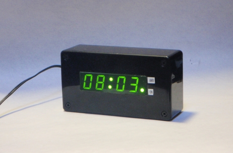
The FlipClock resides in a simple black plastic case lacking any buttons whatsoever. When the alarm goes off, all one needs to do is flip the clock over to disable it. The digits automatically right themselves using an accelerometer to detect when the clock has been turned upside down, and an indicator LED lets you know that the alarm has been turned off.

The clock is based around a Propeller chip, which manages all of the clock’s operations. Instead of using a real time clock IC, [Corbin] is using a GPS module to keep accurate time, something we don’t recall seeing in an alarm clock  before. That’s a good thing though, since there are no buttons with which to set the clock. In fact, there are no buttons to set the alarm either – the clock is configured to sound the alarm at the same time each day.

While this clock would certainly be too dangerous for a chronic snooze button abuser like myself, it’s an interesting concept nonetheless!

Check out the video below to see the FlipClock in action.

Continue reading “Flip Off Your Alarm Clock!”

Interfacing With A PS/2 Keyboard

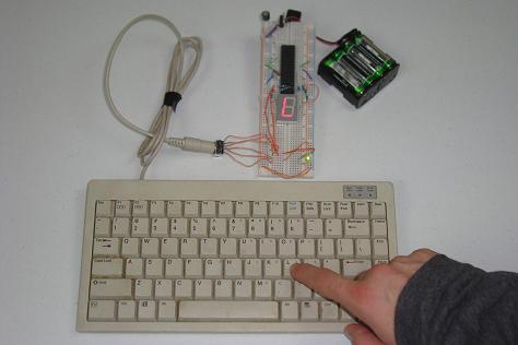
Anyone reading this post has undoubtedly used a keyboard. How they work, however, is a bit more complicated than “one button, one input.”  [PyroElectro] has a great tutorial about building a PS/2 keyboard interface with a 7-segment LED display (video after the break). The tutorial also includes quite a bit of theory behind it.

The system displayed below uses a PIC controller to display the letter or number pressed. A schematic of the whole project is given here as well as a detailed bill of materials.

As for how the PS/2 keyboard works, each keystroke is encoded into a binary number or “scan code”. Most of these codes are 8-bit, but some special symbols use a longer code. Although the article doesn’t fully address it, a very similar method can be used to send data back to the keyboard for such purposes as tuning on a “capslock” or “numlock” key. Although turning on a light is fun, we could see this being used as an expedient method to control a relay for automation purposes.

Continue reading “Interfacing With A PS/2 Keyboard”