Depending on who you believe, yesterday someone either broke an NDA or was the lucky recipient of an Element 14 shipping error. Nevertheless, we were lucky enough to get a glimpse at the new Raspberry Pi Model B+. Today, everything is live, and Adafruit has a great teardown of what’s new, what’s changed, and what’s completely different in this new board.
The biggest question about this new Pi was the CPU: the Broadcom SoC in the models A and B are looking a little long in the tooth right now, and an upgraded CPU would be a very, very welcome addition. There is no change. This is the same 700 MHz Broadcom chip with 512MB of RAM. There will not be a ‘magical, because you’re awesome’ RAM upgrade the original Model B saw early in production, either – there simply aren’t enough address pins in the SoC.
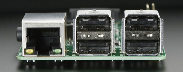
Despite not having an upgraded CPU, there are some neat features that addressed the complaints of the original Pi: The standard sized SD card socket is replaced with a microSD card socket that won’t stick out over the edge of the board. The ports are rearranged, with the analog video out on a TRRS plug with the audio. There are now four USB ports and an Ethernet port thanks to this chip, and mounting holes galore: they’re M2.5 holes in a square 58mm wide and 49mm high. Also included in the B+ is a completely redesigned power supply – the jumbo linear regulator is gone, replaced with an all-around better power supply.
The biggest change for anyone looking making a project with the Pi is the expanded GPIO header. This is a 40 pin header, with the ‘top’ pins identical to the original 26 pin header. Yes, all your existing Pi plates/shields/whatevers will still work. The new pins on this header include nine more GPIO pins, the I2S pins for the Wolfson audio card, and a pair of pins for an ID EEPROM. Connections to an ID EEPROM have been a feature of the BeagleBone for a while now, and this will allow the Pi to configure the appropriate I/Os and kernel modules at boot, depending on what Pi Plates are attached.
The best part about this is the price – it’s the same as the OG Model B. Using the same case as you old Model A or B is out of the question, but that’s totally what Kickstarter is for, right? You might want to grab one of those, because this is probably going to be the form factor for the upgraded Raspberry Pi 2.0 that will probably be released in a year or two.


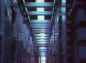 How many Ma Bell employees does it take to build an ESS mainframe? This week, Retrotechtacular takes you into the more poetic recesses of the AT&T Archive to answer that very question. This wordless 1974 gem is
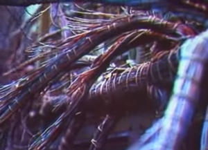
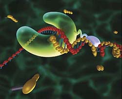 Invented 30 years ago, polymerase chain reaction , or PCR, is one of the greatest inventions of the 20th century. It’s the technique that allows researchers to map genomes, find genetic causes of diseases, create Jurassic Park, and match crime scene DNA to suspects. When PCR was first invented it was extraordinarily expensive, and even today commercial PCR machines cost about the same as a new car. There is an