Hackaday Prize Entry: An SD Card Arduino

About a year ago, Intel announced they’d be launching a new platform stuffed into an SD card. Imagine – an entire computer packaged into an SD card, with nine whole pins for power and I/O. Cooler heads prevailed, the Intel Edison was launched, but the idea stuck; why can’t you fit an Arduino in an SD card?

[kodera2t] found out there’s no real reason why you can’t put a small microcontroller inside an SD card. For his Hackaday Prize entry, he created the SDuino, and it’s exactly what it says on the tin: an ATMega328p stuffed into a microSD adapter.

Unlike the other microcontroller stuffed in an SD card platform — the Electric Imp, [kodera] is, for the most part, respecting the standard pinout for SD cards. The MISO and MOSI signals are reversed, of course, one of the grounds on the SD pinout is tied to an analog input pin on the microcontroller, and the chip select on the SD pinout is ignored completely. Other than that, it’s the closest you’re going to get to an SD card with a microcontroller.


The 2015 Hackaday Prize is sponsored by:

RC Lawn Mower

Electric Lawn Mower Converted To RC Control

Not too many people like pushing a lawn mower around the yard, but unfortunately, it is a necessary chore. Anti-push-mower advocate [imadethis2014] decided to (as his moniker suggests) make a solution to his pushing-problem. He was a fan of radio controlled devices so it made sense to convert his mower to RC!

The mower itself is powered by an off the shelf battery and has a 21-inch deck. The stock wheels and handle were removed and replaced with a new extruded aluminum frame. Out back are a pair of used electric wheelchair motors sourced from eBay. These drive motors are mounted to the new frame via a pair of aluminum brackets that [imadethis2014] designed and cut out on his Shakepoko CNC machine. Since both rear drive wheels work independent of each other, a pair of swiveling casters up front allow the mower to turn.

A large car-sized battery box houses the two smaller wheel chair batteries as well as the motor control and RC electronics. Check out the video after the break, the mower seems to do fairly well. [imadethis2014] admits he needs some new wheels as the current ones don’t get a lot of traction on the grass. He’s also thinking of adding GPS for automated mowing but isn’t quite there yet.

Continue reading “Electric Lawn Mower Converted To RC Control”

Hackaday Links Column Banner

Hackaday Links: June 28, 2015

The iBookGuy is using CPU heatsinks to cool microwave dinners. It’s an old Pentium II heatsink and a modern fan, cobbled together into a device that can quickly and effectively cool down a microwave dinner. I have several heatsinks from some old Xeon servers in my kitchen, but I don’t use them to cool food; I use them to defrost food. It’s very effective, and now I need to get some data on how effective it is.

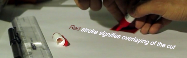
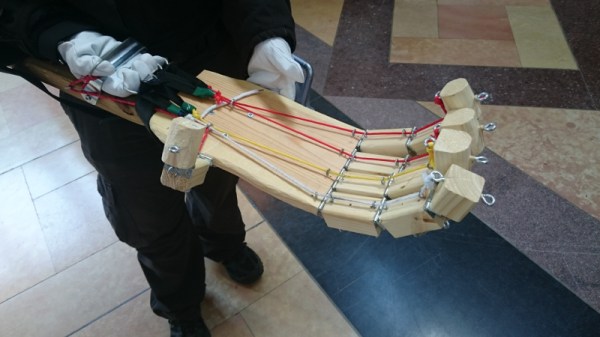
[juangarcia] is working on a 3D printable PipBoy – the one in the upcoming Fallout 4. The extra special edition of Fallout 4 include a PipBoy that works with your cellphone, but if you want one before November, 3D printing is the way to go.

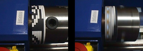
[Collin] over at Adafruit is teaching Oscilloscope Basics. Note the use of the square wave output to teach how to use the controls. Also note the old-school DS1052E; the Rigol 1054Z is now the de facto ‘My First Oscilloscope’

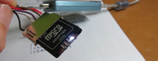
[Donovan] has one of those V212 toy quadcopters. The remote has a switch that controls a bunch of lights on the quad. This switch can be repurposed to control a small camera. All it takes is some wire, an optocoupler, and a bit of solder. Very cool. Video here.

I go to a lot of events where hackers, devs, and engineers spend hours banging away on their laptops. The most popular brand? Apple. The second most popular brand for savvy consumers of electronics? Lenovo, specifically ThinkPad X- and T-series laptops (W-series are too big, and do you really need a workstation graphics card for writing some node app?). They’re great computers, classic works of design, and now there might be a ThinkPad Classic. With a blue Enter key, 7-row keyboard, a multi-color logo, ThinkLights, a bunch of status LEDs, and that weird rubberized paint, it’s a modern realization of what makes a ThinkPad great. Go comment on that Lenovo blog post; the designer is actually listening. Now if we could just get a retina display in a MacBook Air (the one with ports), or get manufacturers to stop shipping displays with worse than 1080 resolution…

Need a fan guard? Know OpenSCAD? Good. Now you have all the fan guards you could ever want. Thanks [fridgefire] for sending this one in.

What You See Is What You (Laser) Cut

WYSIWYG editors revolutionized content management systems, will WYSIWYC interfaces do the same for laser cutters? Unlikely, but we still appreciate the concepts shown here. Chalkaat uses computer vision to trace lines drawn in ink with the cutting power of a laser.

At its core, you simply draw on your work piece with a colored marker and the camera system will ensure the laser traces this line exactly. There is even a proof of concept here for different behavior based on different line color, and the technique is not limited to white paper but can also identify and cut printed materials.

This is a spin on [Anirudh’s] first version which used computer vision with a projector to create a virtual interface for a laser cutter. This time around we can think of a few different uses for this. The obvious is the ability for anyone to use a laser cutter by drawing their designs by hand. Imagine introducing grade-school children to this type of technology by having them draw paper puppets and scenery in advance and have it cut in shop class for use in art projects.

A red arrow indicates cut line, but a pink arrow is used for indicating positioning on a work piece. The example shows a design from a cellphone etched next to a positioning marker. But we could see this used to position expensive things (like a Macbook) for etching. We also think the red marker could be used to make slight adjustments to cut pieces by scribing a work piece with the marker and having the laser cut it away.

This concept is a product of [Nitesh Kadyan] and [Anirudh Sharma] at the Fluid Interfaces group at the MIT Media Lab and is something we could see being built into future laser cutter models. What do you think?

Continue reading “What You See Is What You (Laser) Cut”

3D Printing Binaural Microphones

Binaural audio is probably the coolest thing you can listen to with a pair of headphones. Instead of just a single microphone, binaural recordings use two microphones, set inside an analog for a human head, to replicate exactly what you would hear if you were there.

The only way to record binaural audio is with fake plastic ears attached to a dummy head. Most of the famous microphone manufacturers have something like this, but with a 3D printer, anything is possible. [Carlos] created his own binaural microphone using a 3D printer and went through the trouble of creating a few audio demos. The results are weird, like [Carlos] is whispering into your ear.

The ears used in this microphone setup are taken from a Thingiverse project by [Jonathan March]. This model did not properly model the ear canal,and didn’t have any way to mask the sound from ear to ear; this is why the professional models also include a head. [Carlos] fixed these shortcomings and created a few 3D models that accurately model the human ear and head.

There’s also a simple stereo microphone amplifier for this project that is designed to fit right between the ears. This amplifier was designed in KiCAD, and the PCB is single sided. It’s not quite simple enough to assemble on a piece of stripboard, but [Carlos] did manage to manufacture it on some copper clad board in his mill.

The results? It sounds awesome. [Carlos] put together a demo of his microphone, link below, and it only works if you’re wearing headphones.

Continue reading “3D Printing Binaural Microphones”

Maker Faire Kansas City: Coming To Grips With The Mechanics Of Dexterity

There is always a great variety of things to see and experience at the Kansas City Maker Faire. This is the fifth year for the event which is held at historic Union Station, a beautiful art deco train depot from a bygone era. With a multitude of booths and exhibits across two floors and a vast outdoor area, there is something for pretty much everyone. Often times, the interesting things are mobile conversation-starting creations. When we saw [Dan] walking around with a giant wooden contraption on his arm, we knew we must find out more about it.

The impetus for [Dan]’s project was his desire to pick up a soda can using a mechanical grip. He now believes this to have been a lofty goal, given the weight of a full can of the stuff. This prosthetic hand is made from wooden finger segments that are connected by small, continuous hinges. Each of [Dan]’s gloved fingers curls around a metal ring to control that digit’s large wooden analog. On the inside of the hand, sections of paracord run underneath strategically placed eye bolts on each finger segment and are tied off at the fingertips. A second set of eye bolts on the back of the hand anchor the network of rubber bands that provide resistance. Although he made it look easy to open and close the hand, [Dan] said that it’s pretty heavy to lug around and somewhat strenuous to use. Next time, he’ll probably go with foam or 3D-printed pieces.

2D Printed Tachometer For A Lathe

If you ever wanted a reason to have DC lighting pointed at the spinny part of your mill and lathe, [Bill] tells a great story. One day, he noticed the teeth on his lathe chuck would change color – red, then blue, then red. His conclusion was the fluorescent lights above his workbench was flashing, as fluorescent lights normally do.

Imagine if the teeth on [Bill]’s chuck weren’t painted. They would appear stationary. That’s usually a bad thing when one of the risks of using a lathe is ‘descalping.’ Buy an LED or incandescent work light for your shop.

This unique effect of blinking lights got [Bill] thinking, though. Could these fluorescent lights be used as a strobe light? Could it measure the RPM of the lathe?

And so began [Bill]’s quest for a 2D printed lathe tachometer. The first attempt was to wrap a piece of paper printed with evenly space numbers around the chuck. This did not work. The flash from his fluorescent bulb was too long, and the numbers were just a blur. He moved on to a maximum-contrast pattern those of us who had a ‘DJ phase’ might recognize immediately.

By printing out a piece of paper with alternating black and white bands, [Bill] was able to read off the RPM of his chuck with ease. That’s after he realized fluorescent lights blink twice per cycle, or 120 times a second. If you have a 3″ mini-lathe, [Bill] put the relevant files up, ready to be taped to a chuck.