Hackaday Dictionary: Servo Motors

How do you make things move? You add in a motor that converts electrical energy into motion. That’s a simple idea, but how do you know where the motor is? That’s where the servo motor comes in. By adding a sensor and a controller to the mechanism, these motors can figure out how far they have rotated and maintain that setting without any need for external control.

A disassembled servo motor showing the controller, motor, rotary encoder and gears. By oomlout - SERV-05-ST_TEARDOWN_03, CC BY-SA 2.0
A disassembled servo motor showing the controller, motor, rotary encoder and gears. By oomlout, CC BY-SA 2.0

What is a Servo Motor?

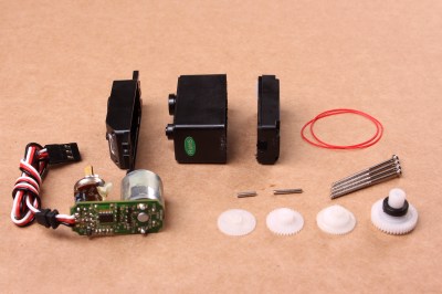
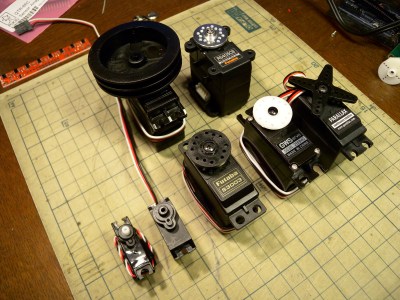
These neat devices can be large or small, but they all share the same basic characteristics: a motor connected to a gearing mechanism and an encoder that detects the movement and speed of the motor. This combination means that the controlling device doesn’t need to know anything about the motor itself: the controller on the servo motor handles the process of feeding the appropriate power to the motor until it reaches the requested position. This makes it much easier to build things with servomotors, as the designer has already done all the hard work for you.

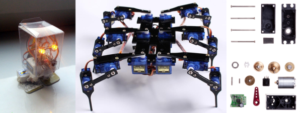
The first place that most people encounter a servo motor is in the small hobby servos that are used in remote control vehicles. Manufactured by companies like Hitec and Futaba, these drive a gear or arm that transfers the rotation of the motor to perform tasks like turning a wheel to steer a car, moving a control surface on an RC plane, or any task that requires a small range of motion at high precision. The gearing in the servomotor offers more torque than connecting the shaft directly to the motor. Most hobby servos of this type are restricted to a certain range of motion (usually 180 degrees) because the position encoder is a simple potentiometer connected to the output shaft.

A selection of different sized servo motors. By Osamu Iwasaki

Servomotors usually have three connection wires: a power line, a ground line and a signal line. The signal line is fed a pulse width modulation (PWM) signal that determines the angle that the servomotor moves to. As the name suggests, the length of the pulse (or the width, if you look at it on an oscilloscope) is the thing that controls the angle that the servo moves to: a short pulse (1 millisecond) sets it to the zero angle, while a long pulse of 2 milliseconds sets it to the maximum angle. A pulse length between these two limits signals the servomotor to move to the corresponding angle: 1.5 ms would set it to 90 degrees.

It is important to note that servomotors and stepper motors are not the same thing. Both are used for positioning, but steppers usually run without feedback. Instead, steppers turn (as the name suggest) in discrete steps. To figure out where a stepper motor is requires a limit switch, then driving the stepper until this is triggered. Then if you keep count out the number of steps that it’s traveled, you know where it is. That’s why devices like inkjet or 3D printers will move to their limits when they start up, so the controller can detect the far limit of the mechanism being driven, and calculate the current position from that.

How Do You Use A Servomotor?

Because the designers of servomotors have done most of the hard work for you, servomotors are very easy to use. To drive them, you just need to feed them power (usually 5V) and feed the PWM signal to the servomotor. You can drive them directly from an Arduino or similar microcontroller using a library that converts an angle into a PWM signal on one of the output pins.

Each servomotor requires a dedicated output pin if they are being driven this way, though, so if you are driving a lot of servomotors, a dedicated controller makes more sense. Devices such as the Adafruit Servo Shield and the Pololu Maestro allow you to control multiple servos from a single output pin on the microcontroller: the microcontroller sends a signal to the device addressing each servo in turn, and the device converts this into the PWM signals for each. If you need to drive a lot of servos, the SD84 can control up to 84 servos at once from a single USB port.

(Headline image bots: µBob and Hexapod4.)

Moldy Rechargeable Batteries

What’s worse than coming in from the workbench for a sandwich only to discover that the bread has molded? That red bread mold–Neurospora crassa–can transform manganese into a mineral composite that may improve rechargeable batteries, according to a recent paper in Current Biology.

Researchers used the carbonized fungal biomass-mineral composite in both lithium ion cells and supercapacitors. The same team earlier showed how fungi could stabilize toxic lead and uranium. Mold, of course, is a type of fungus that grows in multi-cellular filaments. Apparently, the fungal filaments that form are ideal for electrochemical use of manganese oxide. Early tests showed batteries using the new material had excellent stability and exceeded 90% capacity after 200 discharge cycles.

The team plans to continue the use of fungus in various metallurgical contexts, including recovering scarce metal elements. This is probably good news for [Kyle]. This is quite an organic contrast to the usual news about graphene batteries.

Image: Qianwei Li and Geoffrey Michael Gadd

Flying Close To The Flame: Designing Past Specified Limits

A very good question came up on The EEVBlog forum that I thought deserved an in depth answer. The poster asked why would amplifier companies in the heyday of tube technology operate tubes in mass produced circuits well in excess of their published manufacturers recommended limits. The simple answer is: because the could get away with it. So the real question worth exploring is how did they get away with operating outside of their own published limitations? Let’s jump in and take a look at the collection of reasons.

Continue reading “Flying Close To The Flame: Designing Past Specified Limits”

An Affordable Panasonic Grid-EYE Thermal Imaging Camera

Thermal imaging cameras are objects of desire for hackers and makers everywhere, but sadly for us they can be rather expensive. When your sensor costs more than a laptop it puts a brake on hacking.

Thankfully help is at hand, in the form of an affordable evaluation board for the Panasonic Grid-EYE thermal imaging camera sensor. This sensor has sparked the interest of the Hackaday community before, featuring in a project that made the 2014 Hackaday Prize semifinals, but has proved extremely difficult to obtain.

All that has now changed though with this board. It features the Grid-EYE sensor itself, an Atmel ATSAM-D21G18A microcontroller, and onboard Bluetooth, but has an interesting feature that, as well as being a standalone device, can be used as an Arduino shield. A full range of APIs are provided, and the code is BSD licensed.

This module is not the highest-spec thermal imaging camera on the market by any means, after all it has a resolution of only 64 pixels in an 8×8 grid. But its affordability and easy availability should trigger a fresh crop of thermal camera projects in our community, and we applaud that.

Thermal camera projects have featured quite a few times here on Hackaday. Some have been based on the FLIR Lepton module, like this one that combines its image with a 640×480 visible camera and another that claims to be one of the smallest thermal cameras, while others have harnessed raw ingenuity to create a thermal camera without a sensor array. This pan-and tilt design for example, or this ingenious use of light painting. Please, keep them coming!

[via oomlout]

Mirror Monitor Responds To Your Gestures

[DerVonDenBergen] and his friend are working on a pretty slick mirror LCD with motion control called Reflecty — it looks like something straight out of the Iron Man movies or the Minority Report.

Like most mirror monitors they started with a two way mirror and a de-bezelled LCD — but then they added what looks like an art gallery light off the top — but instead of a light bulb, the arm holds a Leap Motion controller, allowing gesture commands to be given to the computer.

The effective range of the Leap Motion controller is about 8-10″ in front of the display allowing you to reach out and point at exactly what you want — and then squeeze your fist to click. A complete gallery of images is available over on Imgur, but stick around after the break to see a video of the display in action — we kind of want one.

Continue reading “Mirror Monitor Responds To Your Gestures”

Growing Algae For Fun And Profit

Supposedly, writes [Severin], algae is a super food, can be used as biofuel, and even be made into yoga mats. So he’s built an algal reactor at Munich Maker Lab, to try to achieve a decent algal yield.

You might expect that  sourcing live algae would be as simple as scraping up a bit of green slime from a nearby pond, but that yields an uncertain mix of species. [Severin] wanted Chlorella algae for his experiment because its high fat content makes it suitable for biodiesel experiments, so had to source his culture from an aquatic shop.

The reactor takes the form of a spiral of transparent plastic tube surrounding a CFL lamp as a light source, all mounted on a lasercut wooden enclosure housing a pump. A separate glass jar forms a reservoir for the algal-rich water. He does not mention whether or not he adds any nutrient to the mix.

Left to its own devices the machine seems to work rather well, a 48 hour session yielding an impressively green algal soup. Sustained running does cause a problem though, the pipes block up with accumulated algae and the machine needs cleaning by blasting it with high pressure water and a healthy dose of nuts and bolts.

This isn’t the first algal reactor we’ve featured here on Hackaday, we had this Arduino-powered one back in 2009. But mostly the algae that have appeared here have been of the bioluminescent variety, as with this teaching project, or this night light.

BlinkenBone Meets The PiDP8

Years ago when the old mainframes made their way out of labs and into the waiting arms of storage closets and surplus stores, a lot got lost. The interesting bits – core memory boards and the like – were cool enough to be saved. Some iconic parts – blinkenlight panels – were stashed away by techs with a respect for our computing history.

For the last few years, [Jörg] has been making these blinkenlight panels work again with his BlinkenBone project. His work turns a BeagleBone into a control box for old console computers, simulating the old CPUs and circuits, allowing them to work like they did thirty years ago, just without the hundreds of pounds of steel and kilowatts of power. Now, [Jörg] has turned to a much smaller and newer blinkenlight panel, the PiDP-8.

The PiDP-8 is a modern, miniaturized reproduction of the classic PDP 8/I, crafted by [Oscar Vermeulen]. We’ve seen [Oscar]’s PiDP a few times over the last year, including a talk [Oscar] gave at last year’s Hackaday Supercon. Having a simulated interface to a replica computer may seem ridiculous, but it’s a great test case for the interface should any older and rarer blnkenlight panels come out of the woodwork.