Building A DIY Flight Yoke For Flight Simulator

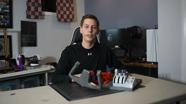
Flight yokes are key to getting an authentic experience when playing a flight simulator, but [Michel Rechtin] didn’t want to pay big money for a commercially-available solution. He ended up building a design using a lot of parts he had laying around, which saved money and worked out great.

The build is based around an Arduino Micro, which reads a series of potentiometers from the yoke and pedals to control pitch, roll, and yaw, A series of buttons are then added to control ancillary functions for the plane and simulator software.

Much of the build uses old 3D printer components, including linear bearings and rods for the pitch axis for smooth operation. There’s even a throttle setup and some more buttons and switches for a more complete flying experience.

Files are available on Thingiverse from anyone looking to replicate [Michael]’s build. We love to see a yoke built from scratch, though we’ve also seen creative builds repurpose PlayStation controllers for the same purpose. Video after the break.

Continue reading “Building A DIY Flight Yoke For Flight Simulator”

Fifty Motored Paraglider Partly Flies, Partly Glides

If there’s one thing you can count on [Peter Sripol] for, it’s for defining the the aviation category of “Don’t Try This At Home.” In the video below the break, [Peter] displays his latest terror of the skies: A powered paraglider backpack that has fifty electric motors. Does it fly? Yes. Was it a success? Eh… mostly.

As [Peter] even says in the video: Don’t try this at home. [Peter] has taken a paraglider, which is essentially a non-rigid fabric wing that to the untrained eye resembles a parachute, and powered it with fifty drone motors taken from other projects. Two motors each are mounted in a push/pull configuration inside a 5×5 array of 3d printed ducts.

While the experiment was essentially a success, it was also a failure due to not having enough power, too little battery life, and overall just not being that great. Does every experiment need to end in absolute success in order to have fun and learn lessons that can be applied to the next iteration? Definitely not! We applaud [Peter] for being willing to fail- although, we have to admit, failing is a lot easier when you’ve already got a parachute of sorts deployed!

Looking for some more don’t-try-this-at-home projects to gawk at? Look no further than [Colin Furze] who like [Peter],  has managed to gain his own Hackaday tag.

Continue reading “Fifty Motored Paraglider Partly Flies, Partly Glides”

Cute Oscilloscope Uses LEDs For Display

Oscilloscopes were once commonly called CROs, for the fact that they relied on cathode ray tubes for display. Since then, technology has moved quickly, and oscilloscopes these days almost entirely rely on modern screens like LCDs. However, [lonesoulsurfer] went a different route with this fun DIY build, creating an oscilloscope with a low-resolution LED display.

Yes, the signals are shown on a 10×10 matrix made up of red LEDs. The individual pixels look nicely diffused and chunky thanks to the fact that [lonesoulsurfer] was able to source square 5mm LEDs for the build. The whole project only uses four ICs – a decade counter and a LM3914 LED driver to run the display, a 555 timer for clock input, and an LM386 op-amp for amplifying incoming signals.

With a mic fitted onboard, the oscilloscope can act as a simple music visualizer, or be used with a probe to investigate actual circuits. It may not be of great enough resolution or precision for fine work, but it’ll at least tell you if your microcontroller’s clock is running properly if you’re scratching your head about the function of a simple project.

We’ve seen some great DIY oscilloscopes over the years, like this neat Arduino-based build. Video after the break.

Continue reading “Cute Oscilloscope Uses LEDs For Display”

You Can Turn Soft Drink Bottles Into Handy Solar Lamps

Solar lights are a popular garden decoration. Of course, they’re available cheaply from most hardware and garden stores, but if you’re more of the DIY type, you might like to build your own. [opengreenenergy] has done just that, using recycled materials for a cheap and simple design.

The design was inspired by the Moser bottle, which is a water-filled bottle used to diffuse sunlight into a room during the day. Instead of sunlight, however, this design uses an LED to provide the light, for decorating a garden or for use when out camping or traveling.

In this design, a solar panel is used to charge a lithium-polymer battery during the day using a LP4060B5F charge controller IC. It’s paired with a AP6685 battery protection IC to ensure the battery is not overly discharged or otherwise damaged in use. When the solar panel stops putting out power when it gets dark, the LED is automatically switched on. It can be set to a low or high brightness to provide more runtime or more light as needed.

All the circuitry is wrapped up in a neat 3D-printed case that allows the hardware to be screwed directly on top of a regular soft drink bottle. Paired with some water in the bottle, and perhaps a little bleach to stave off algal growth, the result is a handy, portable light that also has enough mass to avoid it being blown over easily.

It’s interesting to compare the design to commercial versions that aim to pare costs down to a minimum. Video after the break.

Continue reading “You Can Turn Soft Drink Bottles Into Handy Solar Lamps”

Non-Contact Probe Works Better With A Little More Complexity

Non-contact voltage probes have been around a while and some test equipment now has them built-in. This is one of those things that you probably don’t think about much, but surely it isn’t that hard to detect AC voltage. Turns out there are a lot of circuits floating around that can do it and [nsievers51] tried a bunch. Many didn’t work very well, but the best used a 4069 CMOS hex inverter. A dollar store flashlight provided power, a case, and an LED and the result was a good-looking and effective probe.

The circuit came from the Electronics Library website and is fairly complex for this sort of device. The CMOS inverters have a high input impedance so they pick up the weak signal. Instead of directly driving an LED, two inverters form a ring oscillator that generate pulses around 1 kHz. At that frequency, the LED appears to be on, but battery consumption is less severe. A single 2N2222-style transistor drives the LED.

We’ve seen a number of variations on this tool in the past. Many of them only use transistors.

Continue reading “Non-Contact Probe Works Better With A Little More Complexity”

Converting Your Bike To Electric: Why You Should, And When You Shouldn’t

A decade ago I was lucky enough to work for an employer that offered a bicycle loan scheme to its employees, and I took the opportunity to spend on a Brompton folding bike. This London-made machine is probably one of the more efficiently folding cycles on the market, and has the useful feature of being practical for longer journeys rather than just a quick run from the train. A 3-speed hub gearbox is fine for unhurried touring, but sadly my little folder has always been a bit of a pain on the hills. Thus around the start of the pandemic I splashed out again and bought a Swytch electric upgrade kit for it, and after a few logistical and life upheavals I’ve finally fitted it to the bike. I’ve ridden a few electric bikes but never had my own, so it’s time to sit down and analyse the experience. Is an electric bike something you should have, or not?

A Box Of Bits Becomes An Electric Bike

All the parts of a Swytch kit
All the parts of a Swytch kit. From the Swytch assembly manual.

Swytch sell their kits via crowdfunding rounds, so I’d been on a waiting list for a while and got an early-bird price on my kit. It took quite a while to arrive, much longer than the expected time in mid-2020 because of the pandemic, finally being delivered some time in February last year. It came in a modestly-sized cardboard carton which would be an easy carry on the Brompton’s luggage rack, containing neatly packed a new front wheel with motor, as well as the battery and all sundry parts.

Fitting the kit shouldn’t stretch the capabilities of a Hackaday reader, with probably the trickiest part being the positioning of a Hall-effect sensor near the crank. The kit works by providing a motor assist when you pedal, so part of it is a set of magnets on a plastic disk with various attachments for different cranks and pedal sets. The Brompton front wheel is removed and its tyre and tube transferred to the Swytch one, which is then put on the bike. Once the magnet disk and Hall sensor are attached, the cables follow the existing ones and emerge at the handlebars where a sturdy bracket for the battery box is fitted. Continue reading “Converting Your Bike To Electric: Why You Should, And When You Shouldn’t”

LED Kaleidoscope Uses Induction Power Magic

The kaleidoscope was first invented back in the early 1800s, with the curio known for showing compelling psychedelic patterns as light passes through colored glass and is reflected by mirrors in a tube. [Debra] of Geek Mom Projects recently gave the classic toy a thoroughly modern twist with her own build. (Thread Reader Link).

[Debra]’s kaleidoscope still relies on the typical mirror-tube construction to create reflections upon reflections which generate symmetrical patterns for the viewer. However, instead of colored glass beads lit by external light, she replaced these with so-called “wireless LEDs.” These little bead-like LEDs are fitted with small coils that allow them to be inductively powered without wires when they are placed in the magnetic field generated by a powered coil. Thus, [Debra]’s kaleidoscope works day or night, even in a dark room, since the light is coming from the little beady LEDs themselves.

It’s a great demonstration of wireless LED technology; there’s something almost magical about the tiny free-moving glowing beads. If you don’t want to buy them off the shelf, you can even make your own! Video after the break.

Continue reading “LED Kaleidoscope Uses Induction Power Magic”