Build Your Own Core Rope Memory Module?

[Luizão] wanted to create some hardware to honour the memory of the technology used to put man on the moon and chose the literal core of the project, that of the hardware used to store the software that provided the guidance. We’re talking about the magnetic core rope memory used in the Colossus and Luminary guidance computers. [Luizão] didn’t go totally all out and make a direct copy but instead produced a scaled-down but supersized demo board with just eight cores, each with twelve addressable lines, producing a memory with 96 bits.

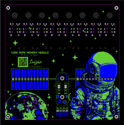
The components chosen are all big honking through-hole parts, reminiscent of those available at the time, nicely laid out in an educational context. You could easily show someone how to re-code the memory with only a screwdriver to hand; no microscope is required for this memory. The board was designed in EasyEDA, and is about as simple as possible. Being an AC system, this operates in a continuous wave fashion rather than a pulsed operation mode, as a practical memory would. A clock input drives a large buffer transistor, which pushes current through one of the address wires via a 12-way rotary switch. The cores then act as transformers. If the address wire passes through the core, the signal is passed to the secondary coil, which feeds a simple rectifying amplifier and lights the corresponding LED. Eight such circuits operate in parallel, one per bit. Extending this would be easy.

Continue reading “Build Your Own Core Rope Memory Module?”

Inside NFC

[Ken Shirriff] likes to take chips apart and this time his target is an NFC chip used in Montreal transit system tickets. As you might expect, the tickets are tiny, cheap, and don’t have any batteries. So how does it work?

The chip itself is tiny at 570 µm × 485 µm. [Ken] compares it to a grain of salt. The ticket has a thin plastic core with a comparatively giant antenna onboard.

Continue reading “Inside NFC”

The Book That Could Have Killed Me

It is funny how sometimes things you think are bad turn out to be good in retrospect. Like many of us, when I was a kid, I was fascinated by science of all kinds. As I got older, I focused a bit more, but that would come later. Living in a small town, there weren’t many recent science and technology books, so you tended to read through the same ones over and over. One day, my library got a copy of the relatively recent book “The Amateur Scientist,” which was a collection of [C. L. Stong’s] Scientific American columns of the same name. [Stong] was an electrical engineer with wide interests, and those columns were amazing. The book only had a snapshot of projects, but they were awesome. The magazine, of course, had even more projects, most of which were outside my budget and even more of them outside my skill set at the time.

If you clicked on the links, you probably went down a very deep rabbit hole, so… welcome back. The book was published in 1960, but the projects were mostly from the 1950s. The 57 projects ranged from building a telescope — the original topic of the column before [Stong] took it over — to using a bathtub to study aerodynamics of model airplanes.

X-Rays

[Harry’s] first radiograph. Not bad!
However, there were two projects that fascinated me and — lucky for me — I never got even close to completing. One was for building an X-ray machine. An amateur named [Harry Simmons] had described his setup complaining that in 23 years he’d never met anyone else who had X-rays as a hobby. Oddly, in those days, it wasn’t a problem that the magazine published his home address.

You needed a few items. An Oudin coil, sort of like a Tesla coil in an autotransformer configuration, generated the necessary high voltage. In fact, it was the Ouidn coil that started the whole thing. [Harry] was using it to power a UV light to test minerals for flourescence. Out of idle curiosity, he replaced the UV bulb with an 01 radio tube. These old tubes had a magnesium coating — a getter — that absorbs stray gas left inside the tube.

Continue reading “The Book That Could Have Killed Me”

Testing Large Language Models For Circuit Board Design Aid

Beyond bothering large language models (LLMs) with funny questions, there’s the general idea that they can act as supporting tools. Theoretically they should be able to assist with parsing and summarizing documents, while answering questions about e.g. electronic design. To test this assumption, [Duncan Haldane] employed three of the more highly praised LLMs to assist with circuit board design. These LLMs were GPT-4o (OpenAI), Claude 3 Opus (Anthropic) and Gemini 1.5 (Google).

The tasks ranged from ‘stupid questions’, like asking the delay per unit length of a trace on a PCB, to finding parts for a design, to designing an entire circuit. Of these tasks, only the ‘parsing datasheets’ task could be considered to be successful. This involved uploading the datasheet for a component (nRF5340) and asking the LLM to make a symbol and footprint, in this case for the text-centric JITX format but KiCad/Altium should be possible too. This did require a few passes, as there were glitches and omissions in the generated footprint.

When it came to picking components for a design, it’s clear that you’re out of luck here unless you’re trying to create a design that a million others have made before you in exactly the same way. This problem got worse when trying to design a circuit and ultimately spit out a netlist, with the best LLM (Claude 3 Opus) giving nonsensical suggestions for filter designs and mucking up even basic amplifier designs, including by sticking decoupling capacitors and random resistors just about everywhere.

Effectively, as a text searching tool it would seem that LLMs can have some use for engineers who are tired of digging through yet another few hundred pages of poorly formatted and non-indexed PDF datasheets, but you still need to be on your toes with every step of the way, as the output from the LLM will all too often be slightly to hilariously wrong.

ESP32 Brings New Features To Classic Geiger Circuit

There’s no shortage of Geiger counter projects based on the old Soviet SBM-20 tube, it’s a classic circuit that’s easy enough even for a beginner to implement — so long as they don’t get bitten by the 400 volts going into the tube, that is. Toss in a microcontroller, and not only does that circuit get even easier to put together and tweak, but now the features and capabilities of the device are only limited by how much code you want to write.

Luckily for us, [Omar Khorshid] isn’t afraid of wrangling some 0s and 1s, and the result is the OpenRad project. In terms of hardware, it’s the standard SBM-20 circuit augmented with a LILYGO ESP32 development board that includes a TFT display. But where this one really shines is the firmware.

With the addition of a few hardware buttons, [Omar] was able to put together a very capable interface that runs locally on the device itself. In addition, the ESP32 serves up a web page that provides some impressive real-time data visualizations. It will even publish its data via MQTT if you want to plug it into your home automation system or other platform.

Between the project’s Hackaday.io page and GitHub repository, [Omar] has done a fantastic job of documenting the project so that others can recreate it. That includes providing the schematics, KiCad files, and Gerbers necessary to not only get the boards produced and assembled, but modified should you want to adapt the base OpenRad design.

This project reminds us of the uRADMonitor, which [Radu Motisan] first introduced in 2014 to bring radiation measuring to the masses. This sort of hardware has become far more accessible over the last decade, bringing the dream of a globally distributed citizen-operated network of radiation and environmental monitors much closer to reality.

Continue reading “ESP32 Brings New Features To Classic Geiger Circuit”

Bit Of OpenSCAD Code Caps Off Wiremold

Wiremold is great stuff — it’s relatively cheap, easy to work with, and offers all sorts of adapters and angle pieces which take the hassle out of running (and hiding) wires. But [Dr. Gerg] found a shortcoming of this otherwise very flexible product: since each run is intended to start and end in a surface mounted box, he couldn’t find an end cap that would let him close off a section.

The solution? A desktop 3D printer and a chunk of OpenSCAD code telling it what to extrude. When you break it down, the Wiremold profile is fairly straightforward, and can be easily described with geometric primitives. A handful of cylinders, a cube or two, tie it all together with the hull() function, and you’re there.

We’d say this would be a fantastic project to cut your OpenSCAD teeth on, but since [Dr. Gerg] was kind enough to share the source code, you don’t have to figure it out on your own. Though there’s still benefit in reading over it if you’re looking for some practical examples of how the “Programmers Solid 3D CAD Modeller” gets things done.

So why would you want a Wiremold endcap? In the case of [Dr. Gerg], it sounds like he was trying to cover up a short run of wire that was running vertically. But we could imagine other applications for this basic design now that it’s out in the wild. For example, a short length of Wiremold outfitted with a pair of printed caps could make for a nice little enclosure if you’ve got a small project that needs protecting.

Kernel Hack Brings Windows XP To The 486

The venerable Intel 486 was released in 1989 as the successor to the extremely popular Intel 386. It was the minimum recommended processor for Windows 98.  (Surprisingly, the Windows 95 minimum was a 386!)  But by the time XP rolled around, you needed at least a 233 MHz Pentium to install. Or at least that was the case until recently when an extremely dedicated user on MSFN named [Dietmar] showed how he hacked the XP kernel so it could run on the classic chip!

The biggest issue preventing XP from working on earlier processors is an instruction introduced on the Pentium: CMPXCHG8B. This instruction compares two 8-byte values and takes different actions depending on an equality test. It either copies the 8 bytes to a destination address or loads it into a 64-bit register. Essentially, it does what it says on the tin: it CoMPares and eXCHanGes some values. If you want to dig into the nitty-gritty details, you can check out this info on the instruction taken from the x86 datasheet.

Without getting too technical, know that this instruction is vital for performance when working with large data structures. This is because one instruction moves 8 bytes at a time, unlike the older CMPXCHG instruction, which only moves a single byte. Essentially, [Dietmar] had to find every usage of CMPXCHG8B and replace it with an equivalent series of CMPXCHG instructions.

On a side note, the once well-known and devastating Pentium F00F bug was caused by a faulty encoding of the CMPXCHG8B instruction. This allowed any user, even unprivileged users, to completely lock up a system, requiring a full reset cycle!

So [Dietmar] was successful, and now you can run the German version of Windows XP on either a real 486 or an emulated one. The installer is available on the Internet Archive and there’s a detailed video below demonstrating installing it on the 86Box virtual machine host.

Continue reading “Kernel Hack Brings Windows XP To The 486”