Cool Tools: Deus Ex Autorouter

The first thing you probably asked yourself when learning how to lay out PCBs was “can’t the computer do this?” which inevitably led to the phrase “never trust the autorouter!”. Even if it hooks up a few traces the result will probably be strange to human eyes; not a design you’d want to use.

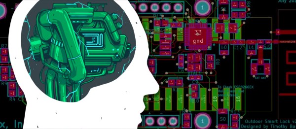
But what if the autorouter was better? What if it was so far removed from the autorouter you know that it was something else? That’s the technology that JITX provides. JITX is a company that has developed new tools that can translate a coarse textual specification of a board to KiCAD outputs autonomously.

Continue reading “Cool Tools: Deus Ex Autorouter”

String Art Robot Is An Autorouter In Reverse

In the depths of Etsy and Pinterest is a fascinating, if tedious, artform. String art, the process of nailing pins in a board and wrapping thread around the perimeter to create shapes and shading, The most popular project in this vein is something like putting the outline of a heart, in string, in the shape of your home state. Something like that, at least.

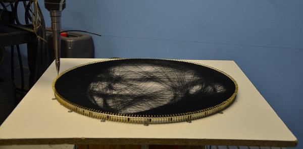
While this artform involves about as much effort as pallet wood furniture, there is an interesting computational aspect of it: you can create images with string art, and doing this is a very, very hard problem to solve with an algorithm. Researchers at TU Wien have brought out the best that string art has to offer. They’ve programmed an industrial robot to create portraits out of string.

The experimental setup for this is about as simple as it gets. It’s a circular frame studded with 256 hooks around the perimeter. An industrial robot arm takes a few kilometers of thread winds a piece of string around one of these hooks, then travels to another hook. Repeat that thousands and thousands of times, and you get a portrait of Ada Lovelace or Albert Einstein.

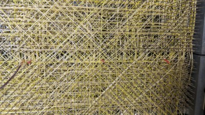
The wire wrapped backplane of a DEC PDP-11. This was assembled by a robot that was programmed with an autorouter. It’s also string art.

The real trick here is the algorithm that takes an image and translates it into the paths the string will take. This is an NP-hard problem, but it is a surprisingly well-studied problem. The first autorouters — the things you should never trust to route traces between the packages on your PCB — we created for wire wrapped computers. Here, computers would find the shortest path between whatever pins had to be connected together. There were, of course, limitations: pins could only have so many connections on them thanks to the nature of wire wrapping, and you couldn’t have one gigantic mass of wires for a parallel bus. The first autorouters were string art algorithms, only in reverse.

You can take a look at the complete publication here.

You’ll also find prior art (tee-hee) in our own pages. Here is an artist doing it by hand, and here’s a machine to do it for you if you’re lazy. We’ve even seen further work on the underlying algorithm on Hackaday.io.

Friday Hack Chat: Trusting The Autorouter

Ah, the autorouter. Inside every PCB design tool, there’s a function called the ‘autorouter’. This function, when used correctly, is able to automagically lay traces between pads, producing a perfect board in under a minute. The trouble is, no one uses it. We have been told not to trust the autorouters and we hear a lot of other dire warnings about it. The autorouter never works. The autorouter will put traces everywhere. The autorouter doesn’t consider floorplanning, and sometimes you’re going to get traces that go right through the edge of your board. Is avoiding the autorouter sound advice?

For this week’s Hack Chat, we’re talking about trusting the autorouter. The autorouter is just a tool, and like any tool, it will do exactly what you tell it. The problem, therefore, is being smart enough to use the autorouter.

Our guest for this week’s Hack Chat is Ben Jordan, Director of Community Tools and Content at Altium. Ben is a Computer Systems engineer, with 25 years experience in board-level hardware and embedded systems design. He picked up a soldering iron at 8, and wrote some assembly at 12. He’s also an expert at using an autorouter successfully.

In this Hack Chat, we’re going to talk to Ben about Altium, Circuit Maker, and how to get the best performance out of an autorouter. How do you set the autorouter up? How do you test your settings? What, actually, is the technology and math that goes into an autorouter? What is the best way to design a multilayer board? How do you do multiboard designs? And what’s the deal with mixed signals?

join-hack-chat

Our Hack Chats are live community events on the Hackaday.io Hack Chat group messaging. This Hack Chat is going down Friday, February 23rd at noon, Pacific time. Want to know what time this is happening in your neck of the woods? Here, look at the neat time zone converter thingy.

Click that speech bubble to the right, and you’ll be taken directly to the Hack Chat group on Hackaday.io.

You don’t have to wait until Friday; join whenever you want and you can see what the community is talking about.

Hackaday Prize Entry: Autorouters Are For The Weak

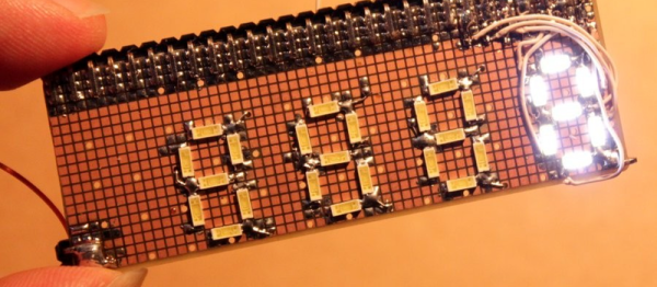
[Yann]’s DYPLED entry into this year’s Hackaday Prize isn’t very useful to most people. It’s a tiny module that connects to a 16-bit parallel bus, and displays a hexadecimal number on a few LEDs. It’s useful if you’re diagnosing a problem on a computer from 1982, but just barely. The real wonder here is how [Yann] is doing this cheaply and easily using some weird techniques and strange parts.

The display for this tiny device is an array of 36 LEDs, arranged into a set of five seven-segment displays. Homebrew seven-segment displays are cool, but how is he driving it? Not with a microcontroller, that’s for sure. Instead, [Yann] is using an old trick of using parallel memory to store the patterns of the seven-segment displays. This parallel memory comes in the form of a two megabit Flash chip, with the data inputs tied to the 16-bit input on the board and the data outputs connected directly to the LEDs. It’s a brute force approach, but it works.

There are a few additional features for this tiny board, including a switch to display a 16-bit bus in hexadecimal or decimal, signed or unsigned, and a pot to change how bright the LEDs are. The most amazing part is how [Yann] managed to fit all of this on a very, very small PCB. Most of that trick is due to using a thin, small TSSOP package for the Flash memory, but fitting this circuit onto a two layer board is amazing work, and a great entry for the Hackaday Prize.

Kicad Autorouting Made Easy

One of the most laborious tasks in PCB layout is the routing. Autorouting isn’t always perfect, but it is nice to have the option, even if you only use it to get started and then hand-tune the resulting board. Unfortunately, recent versions of Kicad have dropped support for autorouting. You can, however, still use Freerouting and the video from [Mr. T] below shows you how to get started.

There are three ways to get the autorouting support. You can install Java and a plugin, you can isntall using a ZIP file, or you can simply export a Specctra DSN file and use Freerouting as a standalone program. Then you import the output DSN file, and you are done.

Continue reading “Kicad Autorouting Made Easy”

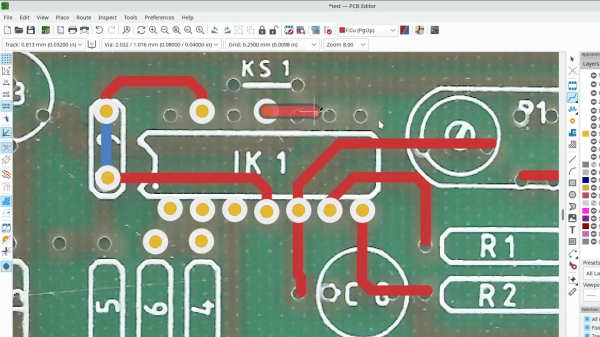
Screenshot of KiCad 7 feature that lets you overlay a PCB bitmap image and draw traces over it, being used for board reverse-engineering purposes

KiCad 7.0.0 Is Here, Brings Trove Of Improvements

Yesterday, the KiCad team has released KiCad 7.0.0 – a surprise for those of us who have only gotten used to the wonders of KiCad 6, and it’s undoubtedly a welcome one! Some of these features, you might’ve seen mentioned in the KiCad 2022 end-of-year recap, and now, we get to play with them in a more stable configuration. There’s a trove of features and fixes for all levels of KiCad users, beginners, hobbyists and professionals alike – let’s start with some that everyone can appreciate! Continue reading “KiCad 7.0.0 Is Here, Brings Trove Of Improvements”

New Release Of FidoCadJ Draws Schematics Everywhere

Do you remember drawing your first schematic? Presumably you used a pen or a pencil and some kind of paper. Schematic capture software, though, makes it so much easier to draw schematics. There are many to choose from, but we spent some time checking out FidoCadJ and found it capable. Of course, there are many other options, but we did like that FidoCadJ runs locally and since it uses Java will run on just about any computer. Since it is open-source, you can modify it and you don’t have to worry about licensing it for your many computers or your team.

The program is a JAR file, and our first attempt to run it ran afoul of our older Java version that was the default Java Runtime Environment. But that was easy to fix, especially since a newer version was there, just not the default.

Continue reading “New Release Of FidoCadJ Draws Schematics Everywhere”