Designing Flip-Flops With Python and Migen

migen

Flip-flops are extremely simple electronic circuits, forming the basis of clock circuits, memory circuits, buffers, and shift registers. Through his dilly-dallying with digital logic, [Jeffrey] decided he would build his own. Not with Verilog or VHDL, though, but Migen: the Python-based way to build digital circuits with software.

Migen is an interesting tool that makes traditional FPGA programming a lot easier; instead of Verilog or VHDL, Migen allows an FPGA to be programmed in Python. Yes, it’s the tool you’ve been waiting for, and the tutorials make it look pretty easy. After installing Migen, [Jeff] wrote a class for a D flip-flop in only three lines of code. That’s three readable lines of code, and he was able to simulate the flip-flop with gtkwave in another two lines. Compared to learning the complexities of VHDL or Verilog, Migen makes digital logic and FPGA programming a breeze.

[Jeff] has a great tutorial for building a D flip-flop with Migen, but we’d love to see some more complex examples of what can be done with this very cool tool. If you’re building (or have built) something with Migen, be sure to send it in and relate your experiences.

Ask Hackaday: What’s Up With This Carbon Fiber Printer?

The Hackaday Tip Line has been ringing with submissions about the Mark Forg3D printer, purportedly the, “world’s first 3D printer that can print carbon fiber.”

Right off the bat, we’re going to call that claim a baldfaced lie. Here’s a Kickstarter from a few months ago that put carbon fiber in PLA filament, making every desktop 3D printer one that can print in carbon fiber.

But perhaps there’s something more here. The Mark Forged site gives little in the way of technical details, but from what we can gather from their promo video, here’s what we have: it’s a very impressive-looking aluminum chassis with a build area of 12″x6.25″x6.25″. There are dual extruders, with (I think) one dedicated to PLA and Nylon, and another to the carbon and fiberglass filaments. Layer height is 0.1mm for the PLA and Nylon, 0.2mm for the composites. Connectivity is through Wifi, USB, or an SD card, with a “cloud based” control interface. Here are the full specs, but you’re not going to get much more than the previous few sentences.

Oh, wait, it’s going to be priced at around $5000, which is, “affordable enough for average consumers to afford.” Try to contain your laughter as you click the ‘read more’ link.

Continue reading “Ask Hackaday: What’s Up With This Carbon Fiber Printer?”

Hackaday Visits The Clark Magnet High School

school

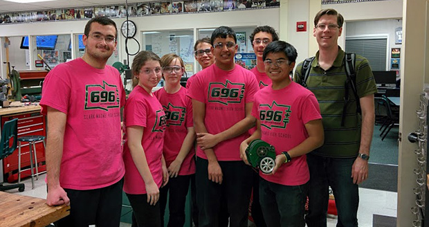
Thought Hackaday’s trip to LA was all about hackerspaces, parties, and rummaging through piles of awesome junk? Nope. We’re also tasked with some community outreach that brought us to the Clark Magnet High School in Glendale, CA.

This isn’t your usual high school. Each year, it accepts around 300 new freshmen (grade 9) from the other high schools in the Glendale district. Selection is done through a lottery system, ensuring it’s not just the kids “on the good side of the tracks” or whose parents are active in the PTA that are selected; about 52% of the students at Clark can be classified as at or below the poverty line.

The curriculum? Instead of stopping at the classical comprehensive high school education, the students at Clark Magnet are focused primarily on the STEM fields. They’re also the home base for Team 696, a FIRST robotics team that has done very well in robotics competitions. A few mentors from JPL and IBM help the students out on their projects, and the head of Clark’s engineering program, [David Black], as well as the principal, were once students themselves.

As far as their engineering program goes, they have a very impressive setup; their workshop features a Haas minimll with a 10-tool carousel, a huge CNC wood router, more than one 3D printer, a small woodshop, a CAD classroom – in short, enough tools to make just about anything. Because Clark Magnet is in sunny California, they’ve been able to get a few grants and build a 358kW peak solar array behind the football field. It’s enough to keep the lights on, and the electric bill down, allowing them to hire an additional teacher or two.

In addition to an impressive engineering/shop class, there’s also an audio and video production suite filled with Mac Pros, cameras, mixing boards and 96 Terabytes of storage. It’s not an exaggeration to say this high school is better equipped than some colleges.

Clark also does some other very interesting stuff outside of class; they’ve launched and recovered high altitude balloons, traveled to elementary schools to play with Lego robots, and some students also have impressive home-built projects they bring in to tinker with. We saw a homebrew quadcopter and a very awesome Mecanum wheel robot that we expect to see in the Hackaday tip line shortly.

Despite how awesome the Clark engineering department is, and how capable the students are, they’ve said the FIRST robotics team has been getting a lot of flak from the rest of the maker community. Apparently some people see an amazing engineering program as a waste of resources. From our short time at Clark, we think nothing could be further from the truth. These students are quickly becoming experts at CAD design and CNC operations. They’re competent embedded programmers and well on their way to becoming awesome engineers. Students who don’t want to build a robot or program firmware get involved in project planning, marketing, and all the rest of the business that goes into running a initiative of this size. It’s a truly awesome program, and I have to say I’m a little bit jealous I didn’t graduate from Clark.

Gallery of pics and two videos below: going over the workshops at Clark and a robot project. Our fanboyism for Clark also demands we link to the (very small and very resonable) Kickstarter the FIRST robotics team is using for their 2014 budget.

Continue reading “Hackaday Visits The Clark Magnet High School”

Veronica Gets A ROM Monitor

monitor

[Quinn] has been on Veronica, her 6502-based computer for quite a while now, but until very recently it’s been more of an embedded project rather than a fully functional computer. Writing software for Veronica on Veronica has been the goal from the start, and finally [Quinn] can write code from a ROM monitor.

In its most basic state, a ROM monitor is an extremely simple piece of software. It resides on the ROM of a computer and is the first thing the computer loads on booting, allowing the user to inspect, read, and write to memory locations, writing code in hex, and running it straight from the monitor.

To write the ROM monitor (and a few other programs), [Quinn] is using the awesome cc65 6502 C compiler. This comes with a whole bunch of macros that make it easy to read keyboard input, shove bits into her AVR GPU, and writing to memory. The monitor program is loaded onto her ROM chip which is automatically read every time the reset button is pressed.

In the video below, you can see [Quinn] writing a few bits to address $2000 that tell the CPU to output ASCII characters to the display. It’s not much, but it’s the first time [Quinn] has written code for Veronica on Veronica, and should prove to be the beginning of a very interesting system.

Continue reading “Veronica Gets A ROM Monitor”

Measuring 185 µΩ In Circuit

meter

To measure resistance, you usually have to take the resistor to be tested out of the circuit, and sometimes that’s impossible. If you’re using a multimeter, measuring very small resistances is difficult to say the least. Combine both these problems – measuring microOhms in-circuit – and you have a problem that’s perfectly suited for the Mooshimeter.

Announced just a few weeks ago, the Mooshimeter is a two-channel multimeter that communicates with your cell phone over Bluetooth. It’s perfect for measuring current and voltage simultaneously, all while being tucked away in some place that’s either dangerous, inaccessible, or mobile.

The Mooshimeter team put together a great example of what can be done with their meter by measuring the resistance of a car battery grounding strap while behind the steering wheel. To do this, they put alligator clips across the grounding cable and clamped on a current meter.

Inside the car, they whipped out their cell phone and looked at the Mooshimeter’s output for the voltage and current measurement. The Mooshi app has an IV curve (with linear regression in the works), so simply dividing the current and voltage gives them the resistance of the battery’s grounding cable.

It’s a very cool and extremely simple demonstration of how cool the Mooshimeter actually is. Video of the demo below.

Continue reading “Measuring 185 µΩ In Circuit”

Toner Transfer PCBs, Double Sided, With Color Silkscreen

Silk

Making a few PCBs with the toner transfer method is a well-known technique in the hacker and maker circles. Double-sided PCBs are a little rarer, but still use the same process as their single-sided cousins. [Necromancer] is taking things up a notch and doing something we’ve never seen before – double-sided PCBs made at home, with color silkscreens, all make with a laser printer.

For laying down an etch mask, [Necro] is using a Samsung ML-2167 laser printer and the usual toner transfer process; print out the board art and laminate it to some copper board.

The soldermasks use a similar process that’s head-slappingly similar and produces great results: once the board is etched, he prints out the solder mask layer of his board, laminates it, and peels off the paper. It’s so simple the only thing we’re left wondering is why no one thought of it before.

Apart from the potential alignment issues for multiple layers, the only thing missing from this fabrication technique is the ability to do plated through holes. Still, with a laser printer, a laminator, and a little bit of ferric or copper chloride you too can make some very nice boards at home.

Flash Game Cartridge For The VIC-20

cart

[Petri]’s first computer was the venerable Commodore VIC-20, predecessor to the Commodore 64. With only 5kB of RAM, a very simple graphics chip, and BASIC, it’s a bare-bones system that’s perfect for a 7-year-old future programmer. [Petri] was trying to figure out something to do with this old computer, and realized the simple schematic would allow him to recreate those classic VIC-20 cartridges using modern hardware.

This project began by cracking open a few game cartridges to see what was inside. They’re very simple devices, consisting of a decoupling cap and a ROM chip wired directly to the data and address busses. [Petri] desoldered the ROM and replaced it with a ribbon cable that would give him a clean breadboard to VIC-20 expansion port interface.

Instead of finding a contemporary EEPROM chip to program, [Petri] decided on using a Flash chip. The original cartridge had a 16kB ROM chip, but the smallest parallel Flash chip he could find was 256k. No problem, then; just ignore a few address lines and everything worked out great.

After getting the VIC-20 reading the breadboarded Flash chip, [Petri] started work on a circuit that would program his Flash chip while still attached to the expansion port. With a few buffer chips and an ATMega32a loaded up with Arduino, he’s able to program the Flash chip and turn it over to the VIC-20.

A simple test that toggled the color of the screen as quickly as possible was all that was needed to test the new circuit. Now, [Petri] can finally start on programming some games for his first love.

Continue reading “Flash Game Cartridge For The VIC-20”