Hackaday Links Column Banner

Hackaday Links: April 22, 2018

Eagle 9 is out. Autodesk is really ramping up the updates to Eagle, so much so it’s becoming annoying. What are the cool bits this time? Busses have been improved, which is great because I’ve rarely seen anyone use busses in Eagle. There’s a new pin breakout thingy that automagically puts green lines on your pins. The smash command has been overhauled and now moving part names and values is somewhat automatic. While these sound like small updates, Autodesk is doing a lot of work here that should have been done a decade ago. It’s great.

Crypto! Bitcoin is climbing up to $9,000 again, so everyone is all-in on their crypto holdings. Here’s an Arduino bitcoin miner. Stats of note: 150 hashes/second for the assembly version, and at this rate you would need 10 billion AVRs to mine a dollar a day. This array of Arduinos would need 2 Gigawatts, and you would be running a loss of about $10 Million per day (minus that one dollar you made).

Are you going to be at Hamvention? Hamvention is the largest amateur radio meetup in the Americas, and this year is going to be no different. Unfortunately, I’ll be dodging cupcake cars that weekend, but there is something of note: a ‘major broadcaster’ is looking for vendors for a ‘vintage tech’ television series. This looks like a Canadian documentary, which adds a little bit of respectability to this bit of reality television (no, really, the film board of Canada is great). They’re looking for weird or wacky pieces of tech, and items that look unique, strange, or spark curiosity. Set your expectations low for this documentary, though; I think we’re all several orders of magnitude more nerd than what would be interesting to a production assistant. ‘Yeah, before there were pushbutton phones, they all had dials… No, they were all attached to the wall…”

The new hotness on Sparkfun is a blinky badge. What we have here is a PCB, coin cell holder, color changing LED, and a pin clasp. It’s really not that different from the Tindie Blinky LED Badge. There is, however, one remarkable difference: the PCB is multicolored. The flowing unicorn locks are brilliant shades of green, blue, yellow, pink, purple, and red. How did they do it? We know full-color PCBs are possible, but this doesn’t look like it’s using a UV printer. Pad printing is another option, but it doesn’t look like that, either. I have no idea how the unicorn is this colorful. Thoughts?

Defcon is canceled, but there’s still a call for demo labs. They’re looking for hackers to show off what they’ve been working on, and to coax attendees into giving feedback on their projects.

Counting Without Transistors

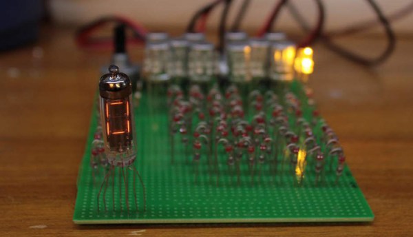
The Hackaday Prize is all about Building Hope. We want to see hardware creators change the world with microcontrollers and breadboards. That’s a noble goal, but it also doesn’t mean you can’t have fun. That’s exactly what [Yann] is doing with a pile of surplus Soviet components, a bunch of bodge wire, and exactly zero transistors. He’s building a hexadecimal display module using only relays and diodes. It’s absurd, but still very very cool.

The inspiration for this build comes from homebrew computing. With this, there’s a recurring problem of displaying the status of a bus. Sure, a bank of LEDs will work, but then you have to count to F. The better solution to this is a hexadecimal display. The best solution to this problem is using Numitrons — seven segment Nixies, basically — and doing it all with relays and diode steering.

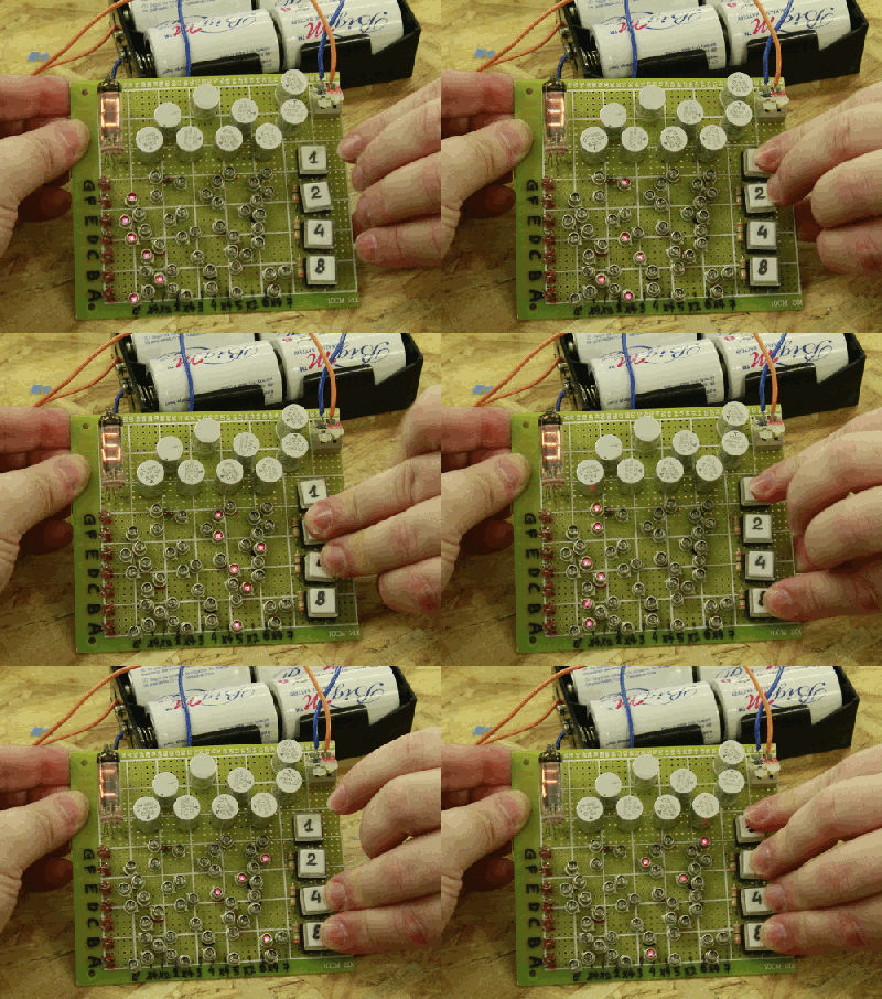
This module accepts four bits as an input and uses a clever arrangement of diodes to turn those four signals into the digits 0-F. Yes, it’s hexadecimal, but that’s just what you do when you’re building your own computer.

Right now, [Yann] has one module on a slim-profile protoboard that should stack easily enough for an 8 or even a 16-bit wide bus. That’s four tubes and hundreds of diodes for the 16-bit version, but the good news is all of these modules are identical, vastly simplifying the construction of the display panel of a homebrew computer.

This Is Your Last Chance To Design The Greatest In Open Hardware

This is the last weekend to get in on the Open Hardware Design Challenge, the first challenge of the 2018 Hackaday Prize. We’re looking for the boldest idea you can come up with. We want to see the beginnings of the next great bit of Open Hardware, and this is your chance to do it.

The Hackaday community has thrown itself into The Hackaday Prize and so far we have more than five hundred entries in the running to Build Hope and become the next great piece of Open Hardware. Next week, we’ll choose the top twenty projects to advance to the finals. Each of those twenty project will be awarded $1,000 and be in the running to win the Grand Prize of $50,000 and four other top cash prizes.

You still have time. This challenge doesn’t require a specific prototype — it’s all about great design. Demonstrate an uplifting use of technology and show a plan to build it. When you make it into the finals, you’ll have all summer to fabricate and refine your vision. This is your chance to be a hardware hero, so start your entry now.

Continue reading “This Is Your Last Chance To Design The Greatest In Open Hardware”

The One-Transistor Flip-Flop

A flip-flop is one of the most basic digital electronic circuits. It can most easily be built from just two transistors, although they can and have been built out of vacuum tubes, NAND and NOR gates, and Minecraft redstone. Conventional wisdom says you can’t build a flip-flop with just one transistor, but here we are. [roelh] has built a flip-flop circuit using only one transistor and some bizarre logic that’s been slowly developing over on hackaday.io.

[roelh]’s single transistor flip-flop is heavily inspired by a few of the strange logic projects we’ve seen over the years. The weirdest, by far, is [Ted Yapo]’s Diode Clock, a digital clock made with diode-diode logic. This is the large-scale proof of concept for the unique family of logic circuits [Ted] came up with that only uses bog-standard diodes to construct arbitrary digital logic.

The single-transistor flip-flop works just like any other flip-flop — there are set and reset pulses, and a feedback loop to keep the whatever state the output is in alive. The key difference here is the addition of a clock signal. This clock, along with a few capacitors and a pair of diodes, give this single transistor the ability to store a single bit of information, just like any other flip-flop.

This is, without a doubt, a really, really weird circuit but falls well into territory that is easily understood despite being completely unfamiliar. The key question here is, ‘why?’. [roelh] says this could be used for homebrew CPUs, although this circuit is trading two transistors for a single transistor, two diodes, and a few more support components. For vacuum tube-based computation, this could be a very interesting idea that someone at IBM in the 40s had, then forgot to write down. Either way, it’s a clever application of diodes and an amazing expression of the creativity that can be found on a breadboard.

Friday Hack Chat: Circuit Board Art

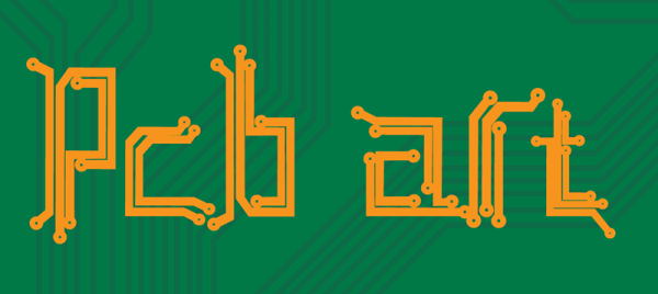
We are now in a golden age of printed circuit boards. It wasn’t too long ago that making your own circuit boards either involved a lot of money, or slightly less money and using some proprietary garbage PCB layout tool. Now, every board house speaks Gerber, and you can get a ten-pack of PCBs from China for five bucks. This incredible cost reduction means people are making art with printed circuit boards. We’ve seen portraits, landscapes, and memes. This is truly the beginning of a new artistic medium rendered in fiberglass and soldermask.

Check out this blinky bit of art nouveau. There is a facebook group for PCB paintings, and some of the Badgelife crew are relying on woodcut and linoleum engraving techniques to create works of art in copper and fiberglass.

For this week’s Hack Chat, we’re going to be talking all about PCB artwork. Our guest for this week’s Hack Chat will be [Andrew Sowa], an electrical engineer, a vocal advocate of KiCad, and the guy who made more of me money. The Benchoff Nickel was created by simply taking some of the fantastic illustrations from Hackaday’s own [Joe Kim] and applying KiCad’s Bitmap2Component tool. Since the creation of the nickel, [Andrew] has been working on extending his technique to cross-hatching, backlighting, and halftones.

In this Hack Chat, we’re going to be talking all about PCB artwork, including the very beginnings of PCB art where engineers hid a few easter eggs in the PCBs of Xboxen and other consumer electronics. Topics covered will be bitmap to SVG conversion (in Inkscape and Illustrator), KiCad footprint creation, and the more technical side of things with the limitations of PCB fabrication and the slightly different shades of beige FR4 comes in.

join-hack-chat

Our Hack Chats are live community events on the Hackaday.io Hack Chat group messaging. This week is just like any other, and we’ll be gathering ’round our video terminals at noon, Pacific, on Friday, April 20th. How can there be time zones when the Earth has four days simultaneously for each rotation? You erroneously measure time from one corner. Here’s a clock counting down the time until the Hack Chat starts.

Click that speech bubble to the right, and you’ll be taken directly to the Hack Chat group on Hackaday.io.

You don’t have to wait until Friday; join whenever you want and you can see what the community is talking about.

Dispensing Solder Paste Automatically

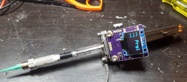
Through-hole chips are slowly falling by the wayside, and if you want to build something with new parts you will be using surface mount components. This means spreading paste and throwing it in the toaster oven. Of course, if you don’t want to take the time to get a stencil for your solder paste, you can always lay it down by hand. For that, [owhite] has created a tiny, handheld, robotic solder paste dispenser. It’s a robotic pen that dispenses just the right amount of solder paste on your pads.

The design of this solder paste dispenser is basically a syringe filled with paste and a stepper motor to push the plunger down. Devices like this already exist, and the i-extruder can be had for somewhere around two hundred bucks. Why buy when you can build, so [owhite] set out to create his own.

The key to a successful solder paste pen, it seems, is driving the plunger with a small NEMA 8 stepper motor, using a very fine pitch on the threads of the gears pushing the plunger down, and surprisingly finding a small-diameter syringe. [owhite] found the last bit in the form of a gas-tight syringe with a nylon gasket. The electronics consist of just a Teensy 3.2, DRV8825 stepper driver, footswitch, and an OLED for a UI.

With just a few parts, [owhite] managed to create a solder paste pen that’s better than the commercial i-extruder, and with a bit of practice can be used to place paste on some SMD pads.

Automating The Design Of Word Clocks

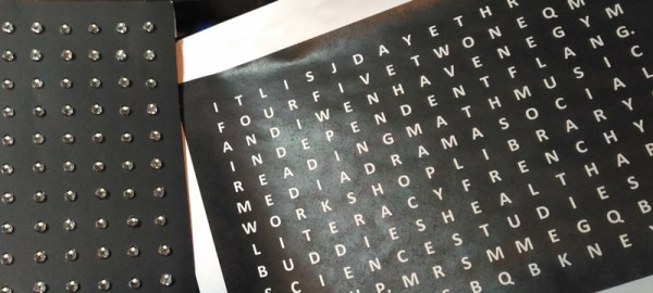
Word clocks, or a matrix of light-up letters that spell out the time, are a standard build for all enterprising electronics enthusiasts. The trouble is finding the right way to drive a matrix of LEDs and the significant amount of brainpower that goes into creating a matrix of letters that will spell out the time without making it look like it’s supposed to spell out the time.

For his Hackaday Prize entry this year, [Stephen Legge] is creating a standard toolkit that makes word clocks easier to build. It’s a hardware and software project, allowing for LED matrices of any reasonable size, and the software to make a grid of letters that only spells out the words you want and not the four-letter ones you don’t.

The hardware for this project is built around the IS31FL3733 LED driver from ISSI. This is an interesting chip that takes I2C in and spits out a LED matrix with very few additional support components. This chip provides [Stephen] with a 12×16 single-color LED matrix, which is more than enough for a word clock.

Where this build gets slightly more interesting is the creation of a custom matrix of letters that will still spell out ‘quarter to noon’ when lit in the appropriate way. This is a big challenge in creating a customized word clock; you could always borrow the layout of the letters from another word clock, but if you want customized phrases, you’ll either have to sit down with a pencil and graph paper, or write some software to do it automatically.

It’s a great project, and since all of [Stephen]’s work is being released under Open Source licenses, it’s a great entry to the first portion of the Hackaday Prize where we’re challenging hardware creators to build Open Hardware.