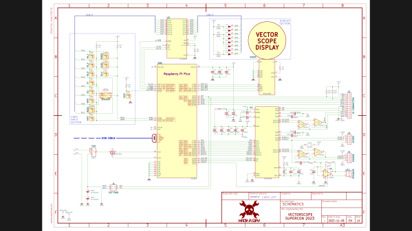
When I saw this year’s Supercon Vectorscope badge, I decided that I had to build one for myself. Since I couldn’t attend in-person, I immediately got the PCBs and parts on order. Noting that the GitHub repository only had the KiCad PCB file and not the associated schematics and project file, I assumed this was because everyone was in a rush during the days leading up to Supercon weekend. I later learned, however, that there really wasn’t a KiCad project — the original design was done in Circuit Maker and the PCB was converted into KiCad. I thought, “how hard can this be?” and decided to try my hand at completing the KiCad project.
Fortunately I didn’t have to start from scratch. The PCB schematics were provided, although only as image files. They are nicely laid out and fortunately don’t suffer the scourge of many schematics these days — “visual net lists” that are neither good schematics nor useful net lists. To the contrary, these schematics, while having a slightly unorthodox top to bottom flow, are an example of good schematic design. Continue reading “Vectorscope KiCad Redrawing Project”→
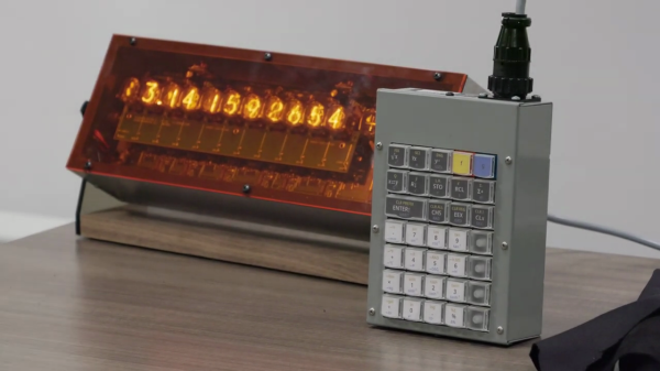
If you like Nixie tubes and/or DIY calculators, checkout this interesting talk from the HP Handheld Conference in Orlando last month by [Eric Smith] from Brouhaha and [John Doran] from Time Fracture. For 20-some years, [Eric] and the late [Richard Ottosen] have been incrementally developing various DIY calculators — this paper from the 2005 HHC conference is an excellent overview of the early project. [John] got one of those early DIY calculators and set about modifying it to use Nixie tubes. However, he got distracted by other things and set it aside — until reviving it earlier this year and enlisting [Eric]’s aid.
This presentation goes over the hardware aspects of the design. Unlike the earlier PIC-based DIY calculators, they decided to use a WCH RISC-V processor this time around. The calculator’s architecture is intentionally modular, with the display and keyboard housed in completely separate enclosures communicating by a serial interface. If the bulkiness alone doesn’t exclude it from being pocket-sized, the 170 VDC power supply and 1/2 W per digit power consumption certainly does. This modularity does lend itself to DIYers replacing the display, or the keyboard, with something different. [Eric] wants to build a mechanical flip-digit display for his unit. As for the software, [Eric] reviews the firmware approach and some future upgrades, such as making it programmable and emulating other flavors of HP calculators.
If you’re embarking on a similar project yourself, check out this talk and take notes — there are a lot of interesting tidbits on using Nixie tubes in the 21st century. If [Eric]’s name sounds familiar, you may know him from the Nonpareil calculator software used on many emulators and DIY calculator projects, one of which we covered some years ago. [John] is also a long-time tinkerer, and we wrote about his gorgeous D16/M HCMOS computer system back in 2012. Thanks to [Stephen Walters] for sending in the tip.
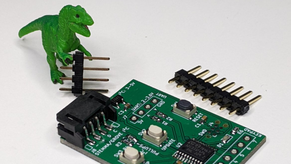
If you’ve scavenged some random keypads and want to reuse them in a project without the hassle of figuring out the pinouts, then [Cliff Biffle] has an interface module for you. The Keypad Go connects to the mystery keypad via an 8-pin 0.1 inch header, and talks to your own project using I2C and/or serial.
You could categorize the mechanism at work as machine learning of a sort, though it’s stretching definitions a bit, as there is no ChatGPT or GitHub Copilot wizardry going on here. But you must teach the module during an initial calibration sequence, assigning a 7-bit ASCII character to each key as you press it. Once trained, it responds to key presses by sending the pre-assigned character over the interface. Likewise, key releases send the same character but with the 8th bit set.
The heart of the board is either an STM32G030 or STM32C011/31, depending on parts availability we presume. I2C connectivity is over a four-pin STEMMA connector, and logic-level serial UART data is over a four-pin 0.1 inch pin header. [Cliff] plans to release the firmware and schematics as open source soon, after cleaning up the code a bit. The device is also for sale on Tindie, though it looks like they won’t be back in stock until later on in the month.
Longtime readers might recognize [Cliff] from his impressive m4vga project which we covered back in 2015, where he manages to generate 800×600 VGA signals at 60 Hz from an STM32F4-family microcontroller.
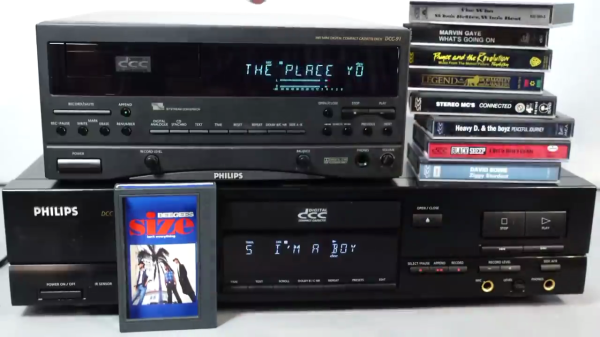
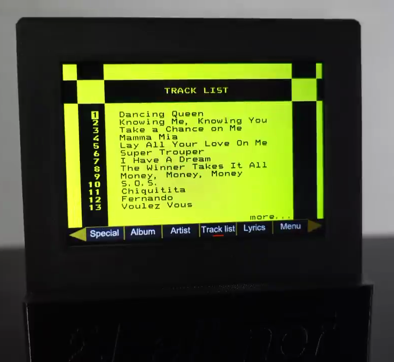
Having a fondness for old and obscure audio and video media formats, [Techmoan] recently revisited the Philips Digital Compact Cassette (DCC) format introduced in 1992. Despite being billed as the successor to Philips’ original analog Compact Cassette format from 1963, DCC was short-lived and slipped away after only four years in 1996. [Techmoan] obtained a unique cassette that purports to be the only known published DCC tape which contains embedded song lyrics that scroll on the DCC player’s tiny screen in sync with the music — “Size Isn’t Everything” by the Bee Gees from 1993. Sure enough, he is able to demonstrate this in the video down below the break.
But, there’s more. For reasons unclear, this only happens on on this one Bee Gees’ album. But it turns out that many DCC tapes did in fact include lots of other metadata, and sometimes lyrics as well. But these were only visible using an unreleased Philips system called Interactive Text Transmission System (ITTS). It just so happens that the folks at the DCC Museum obtained a Philips prototype ITTS box and have been gradually hacking the protocol.
Track Listing Using Blocky Graphics
[Techmoan] demonstrates a modernized prototype version from Germany designed by [Thomas Falkner] called the ITTS video box NG. Using this, he runs through a bunch of DCC tapes from his collection, and finds a significant number of them were published with lyrics and metadata, presumably in anticipation of as ITTS launch. It’s interesting to see how some publishers spent a lot of effort to format this information and others seemed to just copy / paste over the bare minimum.
The more elaborate pages resemble what you might see on your teletext screens back in the day. On those albums that do have lyrics, the presentation can be different, as well. Lyrics from the Bee Gees album appear like text scrolling up on a terminal, with current phrases shown in yellow. Another album’s lyrics can be scrolled in different peculiar ways, including a one-word-at-a-time mode.
If this kind of historical dive into technology interests you, check out the talk that [Jac] and [Ralf] gave at the 2022 Supercon about DCC, and this video from 2018 where [Ralf] digs deeper into this topic. Also, [Jac] has some more recent details on hacking the protocol posted over on his Hackaday.io project page. If you want a more basic introduction to DCC, [Techmoan] introduced this format some years ago on his YouTube channel.
[Jeff Geerling]’s latest project is for the birds — literally. Even though he has a brand new high-speed fiber optic internet connection, online backups of YouTube video projects still take hours. He decided to see if the conclusions from a 2009 in South Africa study still hold true today — that using carrier pigeons to send files can be faster than the internet. [Jeff] sets up an experiment to send 3 TB of data by homing pigeon a distance of one mile to establish a baseline. Next, [Jeff] sends the same 3 TB of data over the internet, and donning the cap of honorary pigeon, simultaneously embarks on a journey by air to his off-site backup service in Nova Scotia, Canada.
Never underestimate the bandwidth of a station wagon full of tapes hurtling down the highway.
[Jeff] points out that you also have to consider the transfer time of your files onto and from the pigeon-suitable memory cards. He jumped through several hoops to minimize that, but it still consumed 2-1/2 hours total. Trying to keep the comparison fair, he also spent a couple days optimizing his internet connection to eek out the best possible speed. Continue reading “Is A Pigeon Faster Than The Internet?”→
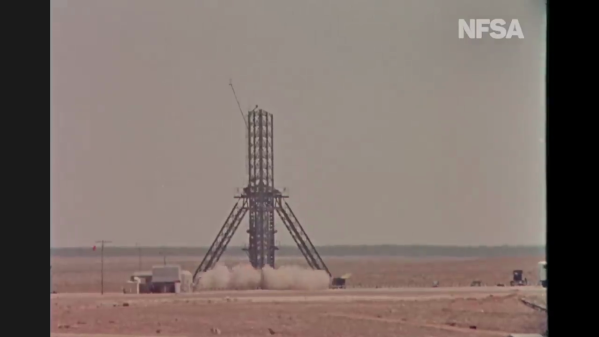
The Film and Sound Archive (NFSA) of Australia just released a digitized version of a 1957 film documentary on Australia’s rocket research back in the day ( see video below the break ). The Woomera test range is an isolated place about 500 km northwest of Adelaide ( 2021 population 132 ) and hosts a small village, an airstrip, and launch facilities. In the Salisbury suburb of Adelaide, a former WW2 munitions factory complex was repurposed as a research center for rockets and long range weapons.
The documentary showcases a wide variety of state-of-the-art technologies from the late 1950s. As ancient as those appear today, a lot of the basic concepts haven’t changed — careful choreography of the launch countdown sequence of events, the antenna and radio systems to receive and store rocket telemetry, photographic records of the rocket in flight, and post-flight analyses of everything to fix problems and improve your designs. They tried to do as much as possible at the Salisbury campus, because as the narrator notes, it’s expensive to work at the distant test range, a concept which is still a consideration today. There’s even a glimpse of the residents’ leisure life in the barren village. It was a different time, to say the least. Continue reading “Rocket Range Australia, 1950s Style”→
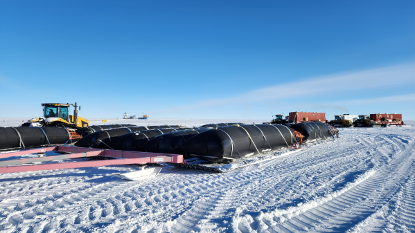
In case you’ve ever wondered how the South Pole research stations are powered, then a recent blog post, South Pole Electrical Infrastructure by anonymous IT engineer [brr] is for you. Among the many issues covered, let’s look at how the electricity is made and, spoiler alert, how the specially formulated AN8 fuel blend is transported to the generators.
The main source of power is a trio of Caterpillar 3512B diesel generator sets, de-rated to 750 kW each due to the high altitude and the special fuel mixture. Unsurprisingly, all the fuel must be imported to Antarctica, a horribly inefficient endeavor. Fuel arrives initially at McMurdo Station harbor by tanker ship. From there, it can be sent to the Amundsen-Scott South Pole Station in one of two ways. The Lockheed LC-130 is a modified C-130 Hercules cargo plane developed in the 1950s specifically to support polar operations. It is the least efficient method, consuming 1.33 kg to transport 1 kg of fuel. Alternatively, fuel can be dragged by tractors via the South Pole Overland Traverse (SPoT), a 1600 km highway over compacted snow and ice. The trek takes about 40 days and only consumes 0.56 kg of fuel for every 1 kg, which is much better than air.